Grove Published 7-23-2020, Control # 668-02 3-15
GRT9165 OPERATOR MANUAL OPERATING CONTROLS AND FEATURES
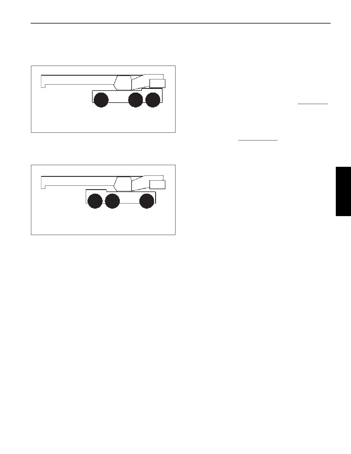
The GRT9165 crane can be driven in the Standard Driving
Configuration—with the boom centered over the front (single
axle). This Standard Driving Configuration is shown in
Figure 3-10.
The GRT9165 crane can also be driven in the Alternate
Driving Configuration—with the boom centered over the rear
(tandem axles). This Alternate Driving Configuration is
shown in Figure 3-11.
The Steering Reversal Switch is used to reverse the driving
controls when changing between Standard Driving
Configuration and Alternate Driving Configuration.
In the Standard Driving Configuration, all driving controls,
including the steering wheel, turn signal lever control,
transmission shift lever control, and the rear steer switch
operate in a certain manner.
In the Alternate Driving Configuration, the operation of these
same driving controls can be reversed for them to continue
to operate in the same manner. Thus, before driving in the
Alternate Driving configuration, the operator will use the
Steering Reversal Switch to reverse these driving controls.
Before the driving controls can be reversed, the following
conditions must be met:
• Crane is stopped
• Service Brake pedal is pushed and held
• Transmission Shift Lever is in Neutral position
Before driving the crane in the Alternate Driving
Configuration with the boom centered over the rear (tandem
axles), push the Steering Reversal Switch one time to
reverse all driving controls including the steering wheel, turn
signal lever control, transmission shift lever control, and the
rear steer switch. The Steering Reversed Indicator in the
Alerts Area (1, Figure 4-74) and Crane Status Area
(4, Figure 4-74) of the Operator Display Module (ODM)
comes on to indicate that these driving controls are reversed
.
When the boom is swung back and centered over the front
(single axle), push the Steering Reversal Switch again to set
the driving controls back to normal operation. The Steering
Reversed Indicator on the ODM goes off to indicate that
these driving controls are not reversed
.
Before driving the crane, read, understand, and follow the
directions found in these sections of this Operator Manual:
• Steering Wheel, page 3-5
• Standard Driving Configuration, page 3-5
• Alternate Driving Configuration, page 3-6
• Turn Signal Lever and Horn Controls, page 3-6
• Transmission Shift Lever, page 3-8
• Steering Reversal Switch, page 3-14
• Rear Steer Switch, page 3-28
Emergency Stop Button
The Emergency Stop Button (17, Figure 3-9) is located on
the right overhead control panel.
Push red button in to stop the engine and all crane functions.
When Emergency Stop Button is pushed in, the Emergency
Stop Active Indicator in the Alerts Area (1, Figure 4-74) of the
Operator Display Module (ODM) comes on.
Rotate and pull out Emergency Stop Button to allow engine
to be re-started and resume normal operation.
Cab Dome Light
The Cab Dome Light (18, Figure 3-9) is located on the right
overhead control panel.
The dome light has a touch control feature. Touch the light
one time to cause it to come on. Touch the light again to
cause it to go off.
FIGURE 3-10
Standard Driving Configuration
9898-1
FIGURE 3-11
Alternate Driving Configuration
9898-2

 Loading...


