Grove Published 7-23-2020, Control # 668-02 5-47
GRT9165 OPERATOR MANUAL SET-UP AND INSTALLATION
Boom Extension Pin Interlock Mechanism
The boom extension pin interlock mechanism (1,
Figure 5-31) interlocks the front mounting pin (3) and boom
installation pins (4) to ensure that the boom extension is
deployed and stowed safely. The front mounting bracket pin
(3) is extended and retracted electrically from the ODM in the
operator cab. Push/pull cables (2) connect the front
mounting bracket pin (3) and boom nose installation pins (4).
When the front mounting pin is extended, the cables (2)
retract the interlock pins from the boom installation pins (4),
unlocking them. When the front mounting pin (3) is retracted,
the cables (2) insert the interlock pins in the boom installation
pins (4), locking them in the extended position. If the boom
installation pins (4) are unlocked, the front mounting pin
cannot be retracted.
Front Boom Extension Mounting Pin
The front boom extension mounting pin (3, Figure 5-31) is
electrically actuated from the ODM in the operator cab.
When the front mounting pin is extended, the boom nose
installation pins (4) are unlocked, allowing the installation
pins to be extended or retracted. When the mounting pin is
extended, the proximity sensor in the front mounting bracket
signals the control system that the front mounting pin is
properly installed. When the front mounting pin is retracted,
no signal is sent to the control system.
Boom Nose Installation Pins
The boom nose installation pins (4, Figure 5-31) are used as
a pivot to deploy the boom extension on to the boom nose
and stow the boom extension on the side of the boom base
section. Mechanical interlock pins lock and unlock the
installation pins (4) based on the position of the front
mounting pin (3). When the front mounting pin (3) is
retracted, the front mounting pin (3) is removed from the front
mounting bracket and the boom nose installation pins (4) are
locked in the extended position. When the front mounting pin
(3) is extended, the installation pins (4) are unlocked,
allowing the installation pins to be extended or retracted. An
impact drill is required to extend and retract the boom nose
installation pins.
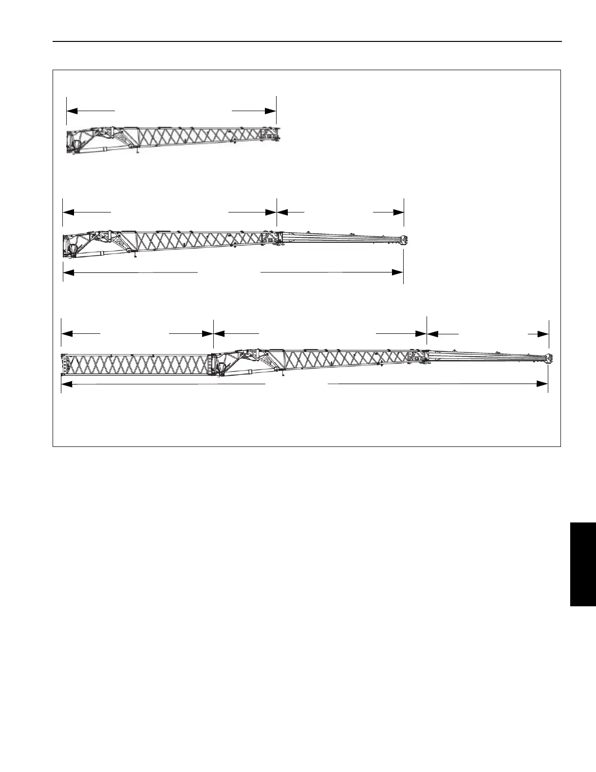
Boom Extension Base Section
Fly Section Stowed on Main
Boom
Fly Section
6.6 m (21.7 ft)
Boom Extension Base Section
11.2 m (35.8 ft)
Boom Extension Base Section
10.9 m (35.8 ft)
Lattice Insert
8m (26.2ft)
Boom Extension Base Section
11.2 m (36.7 ft)
Fly Section
6.6 m (21.7 ft)
Boom Extension Base Section
Fly Section Deployed
Lattice Insert and
Boom Extension Base Section
Fly Section Deployed
17.8 m (58.4 ft)
25.8 m (84.6 ft)
FIGURE 5-30
9964
9965
9966

 Loading...


