5-84 Published 7-23-2020, Control # 668-02
SET-UP AND INSTALLATION GRT9165 OPERATOR MANUAL
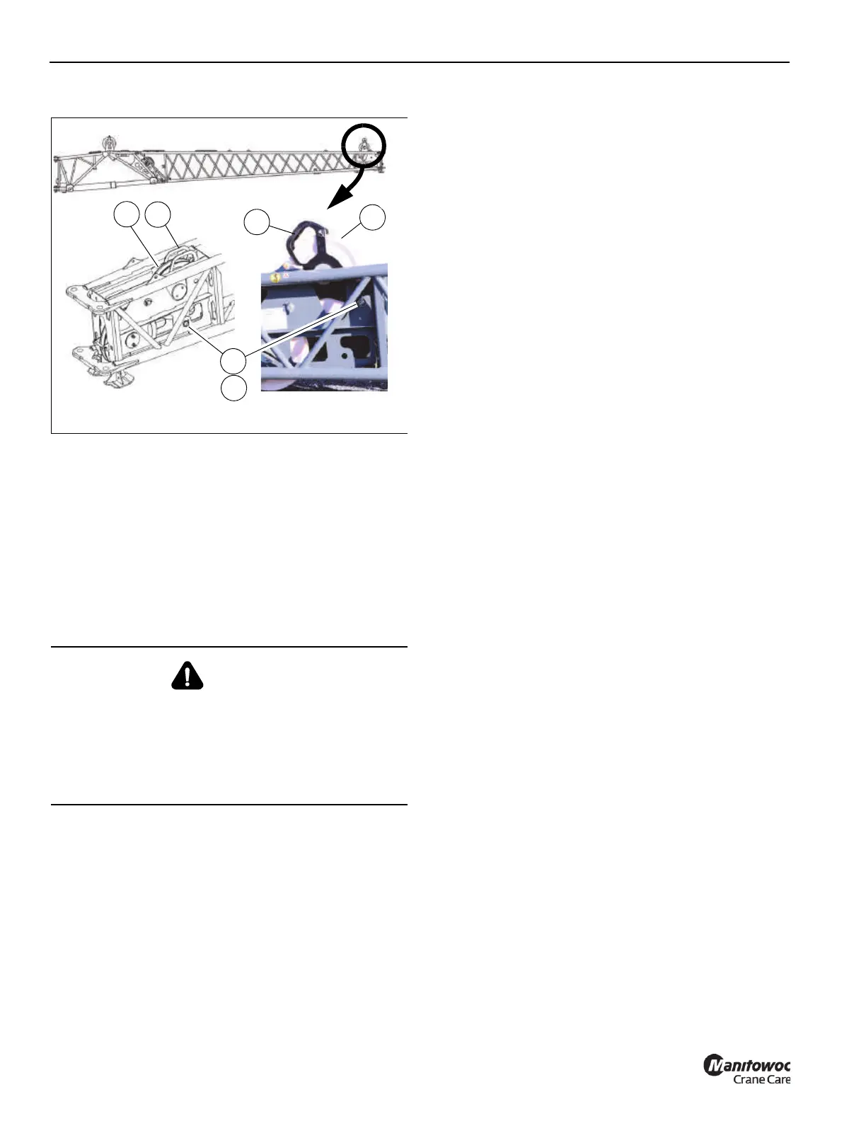
11. Raise the front mast assembly as follows:
a. Hold the handle (1, Figure 5-72) of the mast sheave
assembly (2). Remove retaining clip (3) and pin (4).
b. Raise the mast assembly (2) until the connecting
holes are aligned.
c. Insert pin (4) and secure with retaining clip (3).
12. Deploy the fly section as necessary. For more
information, see Erecting the Fly Section, page 5-62.
Removing the Boom Extension from the
Lattice Insert
1. Make sure the crane is set up on fully extended
outriggers. For more information, see Using the
Outriggers, page 4-21.
NOTE: An auxiliary crane with sling is required to install
the boom extension on the boom nose.
2. Retract and lower the boom to horizontal.
3. Tie a tag line to the boom extension (1, Figure 5-70).
4. Unreeve the hoist rope. For more information, see Hoist
Rope Reeving, page 5-34.
5. Stow the rear mast assembly as follows:
a. Hold the handle (1, Figure 5-71) and remove the
retaining clip (2) and pin (3).
b. Lower the mast (4). Make sure the connecting point
holes are aligned.
c. Insert Pin (3). Secure the pin with retaining clip (2).
6. Stow the front mast assembly as follows:
a. Hold the handle (1, Figure 5-72) of the mast sheave
assembly. Remove retaining clip (3) and pin (4).
b. Lower the mast assembly (2) until the connecting
holes are aligned.
c. Insert pin (4) and secure with retaining clip (3).
7. Remove the anti-two block switch. For more information,
see Anti-Two Block (A2B) Switch, page 5-32.
8. Disconnect the boom extension electrical connector
from the lattice insert. For more information, see Boom
Extension and Lattice Insert Electrical Connections,
page 5-72.
9. If removing a hydraulic boom extension, disconnect the
hydraulic hoses. For more information, see Boom
Extension-to-Lattice Insert Hydraulic Connections, page
5-85.
10. Stow the fly section as necessary. For more information,
see Stowing the Fly Section, page 5-64.
11. Attach a sling and auxiliary crane to the boom extension.
For more information about attaching points for the sling,
see Lifting Points, page 5-50.
12. Remove retaining clips (4, Figure 5-70) and pins (3).
13. Lift the boom extension and fly section (1) from the front
of the lattice insert (2) with the auxiliary crane. Place the
boom extension on a suitable surface.
14. Remove the sling from the boom extension.
15. Remove the lattice insert from the boom nose. For more
information, see Removing the Lattice Insert from the
Boom Nose, page 5-85.
DANGER
Boom Extension Hazard!
To avoid death or serious injury, follow procedures and
cautions in the Operator and Safety Manuals and decals
during erection, stowage and use of boom extension.
Install and secure all pins properly and control boom
extension movement at all times.
Lowered Position Raised Position
FIGURE 5-72
1
1
2
3
4
2
9912
9913
10004

 Loading...


