Section 5847 User Instructions
Issue AL, July 24, 2006 Spec. Nos. 586505000 and 5865055000 (Model LMS1000)
Page 2-62 Chapter 2. Operating LMS1000
This document is property of Emerson Network Power, Energy Systems, North America, Inc. and contains confidential and proprietary information owned by Emerson Network Power, Energy
Systems, North America, Inc. Any copying, use, or disclosure of it without the written permission of Emerson Network Power, Energy Systems, North America, Inc. is strictly prohibited.
LMS ALARM LIMIT OPTIONS
LMS v6.3 contains an enhanced version of alarm processing that allows for a more
intuitive use of alarm limits when used with plant voltage and battery shunts. The new
capability is made possible with an additional analog channel configuration item, alarm
polarity, which governs how high and low alarms operate. The default alarm processing
is the same as earlier LMS revisions – a high alarm occurs when the reading is greater
than the high limit, and a low alarm occurs when the reading is less than the low limit.
LMS v6.3 introduces two new modes of operation intended for analog inputs that have
bipolar or negative readings.
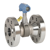
• In the polarized mode, a high or low alarm can
only occur if the polarity of the alarm matches
the polarity of the reading. This is useful for
detecting both high charge and discharge
currents on a battery shunt. For example,
assume a shunt is wired for a negative float
current reading, and it has a high alarm limit of
–6.0 amps to detect a high float current. It
can then also have a high limit of +100.0
amps to detect a high discharge current. So,
in this example there are two high alarms, with
opposite polarity. In previous versions of
LMS, this was not permitted. To select the
polarized mode, enter a “P” at the alarm
polarity prompt.
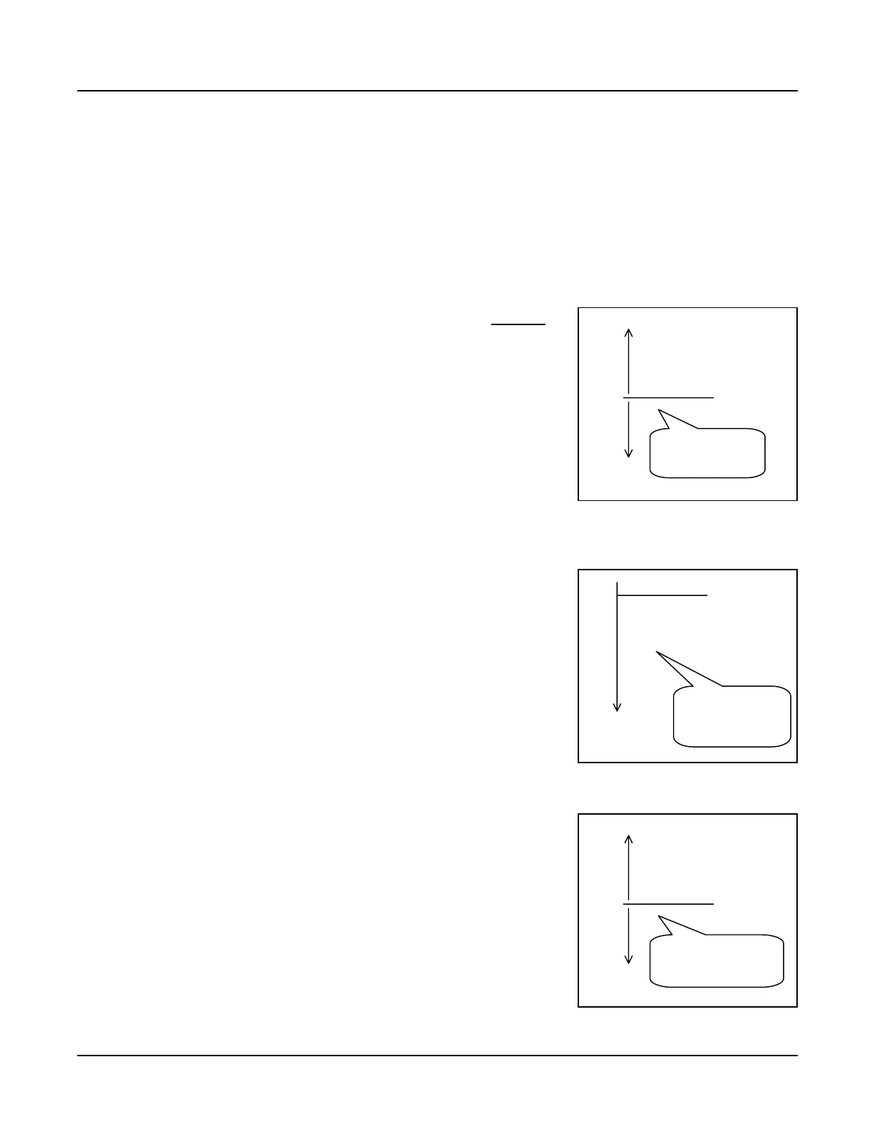
• In the negative mode, the alarm processing is
reversed from the default behavior. In other
words, a high alarm occurs when the reading
is less than the high limit, and a low alarm
occurs when the reading is the greater than
low limit. This is intended for inputs when the
reading is always negative, such as plant
voltage, making it possible to have
conventional alarm limits. Now, -56.0V can
be a high limit (given a float voltage of
-54.0V), when in previous LMS versions, it
must be a low limit. To select the negative
mode, enter a “–“ (minus sign) at the alarm
polarity prompt.
• In the default mode, the polarity of readings
and alarm limits are in fact used during alarm
processing, meaning evaluations are relative
(and not absolute). Furthermore, a reading is
compared to all alarm limits. So, in the
example at right and with a temperature of
-4.0 °C, two low alarms would turn in: one for
+5.0 limit and one for the -3.0 limit. The
default mode can be selected by entering a
“+“ (plus sign) at the alarm polarity prompt.
0
Amps
Charge
egative alarm limits
are only used when the
reading is negative.
Limit 1 -6.0 H
Limit 2 100.0 H
0
-Volts
With v6.3, the –48.0
limit can now be a low
limit, while the –54.0
limit can be a hi
h.
Limit 1 -54.0 H
Limit 2 -48.0 L
0
Temp
In the default mode, it is
possible to have low alarms
above and below zero
Limit 2 5.0 L
Limit 3 30.0 H
Limit 1 -3.0 L

 Loading...