FI SYSTEM DIAGNOSIS 4-25
“C13” IAP SENSOR CIRCUIT MALFUNCTION
INSPECTION
Step 1
1) Lift and support the fuel tank. ("5-7)
2) Turn the ignition switch OFF.
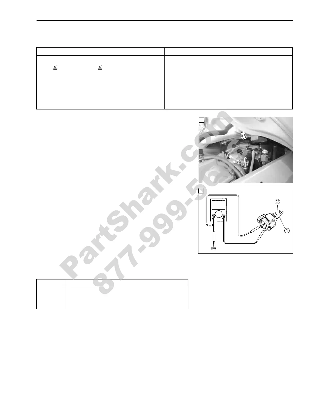
3) Check the IAP sensor coupler for loose or poor contacts.
If OK, then measure the IAP sensor input voltage.
4) Disconnect the IAP sensor coupler.
5) Turn the ignition switch ON.
6) Measure the voltage at the Red wire
1 and ground.
If OK, then measure the voltage at the Red wire
1 and B/Br
wire
2.
% IAP sensor input voltage: 4.5 – 5.5 V
(
+ Red –
- Ground)
(
+ Red –
- B/Br)
! 09900-25008: Multi circuit tester set
' Tester knob indication: Voltage (()
Is the voltage OK?
DETECTED CONDITION POSSIBLE CAUSE
IAP sensor voltage is out of the specified range.
0.1 V Sensor voltage 4.8 V
NOTE:
Note that atmospheric pressure varies depending on
weather conditions as well as altitude.
Take that into consideration when inspecting volt-
age.
• Clogged vacuum passage between throttle body
and IAP sensor.
• Air being drawn from vacuum passage between
throttle body and IAP sensor.
• IAP sensor circuit open or shorted to ground.
• IAP sensor malfunction.
• ECM malfunction.
1
YES Go to Step 2
NO
• Loose or poor contacts on the ECM coupler.
• Open or short circuit in the Red wire or B/Br
wire.
1
V
PartShark.com
877-999-5686
 Loading...


