5-28 FUEL SYSTEM AND THROTTLE BODY
• Connect the fuel injector couplers to the fuel injectors.
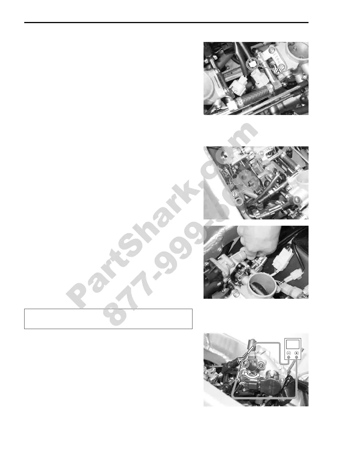
NOTE:
* The fuel injector coupler No.1 (FRONT) can be distinguished
from that of the No.2 (REAR) by the “F” mark
A
.
* Adjust the throttle cable play with the cable adjusters.
Refer to page 2-15 for details.
STP SENSOR ADJUSTMENT
If the STP sensor adjustment is necessary, measure the sensor
resistance and adjust the STP sensor positioning as follows:
• Disconnect the STVA coupler
1 and turn the ignition switch
ON.
• To set the ST valve to fully open position.
• Measure the STP sensor voltage at fully open position.
% STP sensor voltage
ST valve is fully opened: Approx. 4.38 V and more
(Yellow – Black)
$ 09900-25008: Multi circuit tester set
09900-25009: Needle pointed probe set
* Tester knob indication: Voltage (+)
"
• Loosen the STP sensor mounting screws.
• Adjust the STP sensor until voltage is within specification and
tighten the STP sensor mounting screws.
$ 09930-11960: Torx wrench
' STP sensor mounting screw:
2.0 N·m (0.2 kgf-m, 1.5 lb-ft)
AIR CLEANER BOX INSTALLATION
Installation is in the reveres order of removal.
Do not use the tool for turning the STVA shaft to pre-
vent breakdown.
V
PartShark.com
877-999-5686
 Loading...


