8-20 ELECTRICAL SYSTEM
SIDE-STAND/IGNITION INTERLOCK
SYSTEM PARTS INSPECTION
Check the interlock system for proper operation. If the interlock
system does not operate properly, check each component for
damage or abnormalities. If any abnormality is found, replace
the component with a new one.
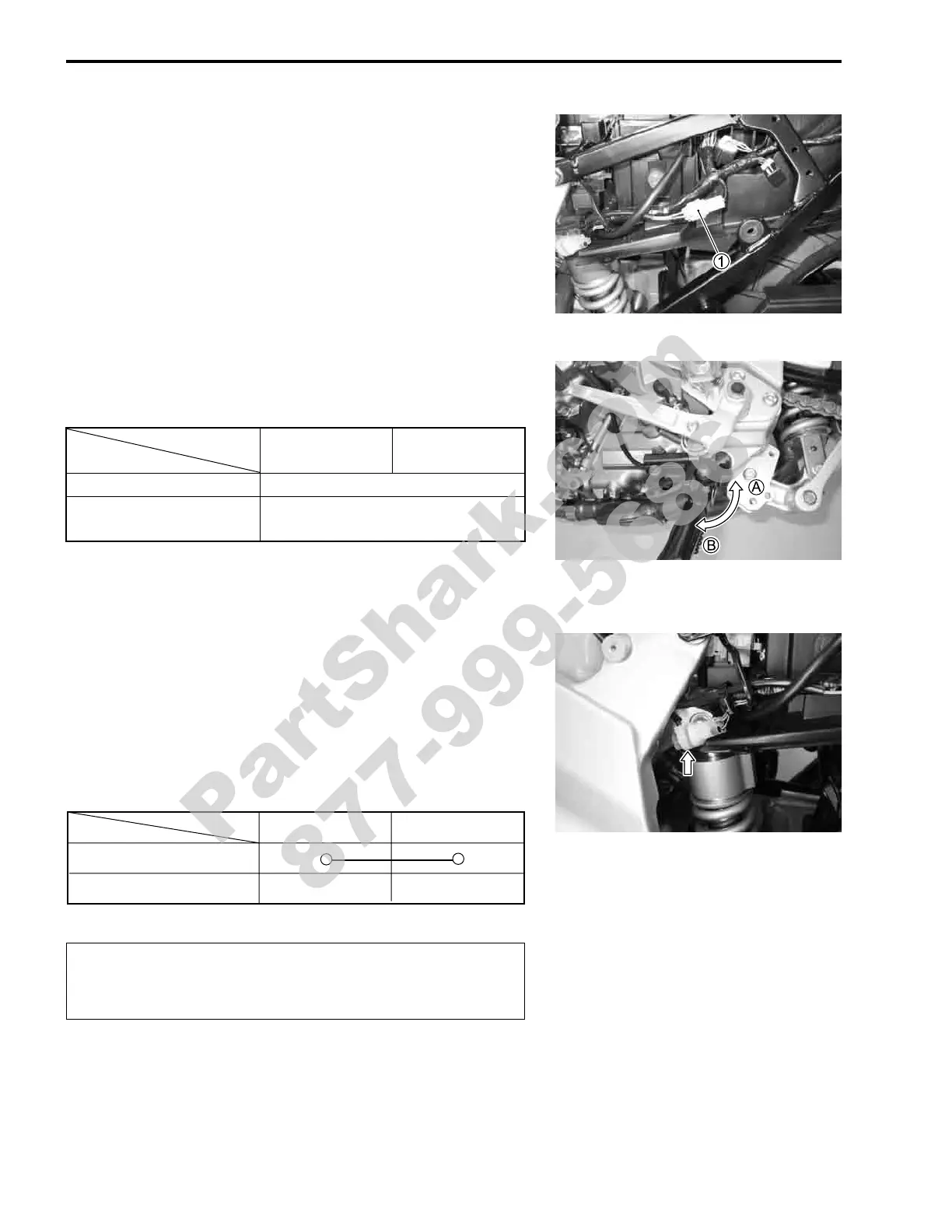
SIDE-STAND SWITCH
• Remove the left frame cover. (!7-5)
• Disconnect the side-stand switch coupler
1 and measure the
voltage between Black/White and Green lead wires.
# 09900-25008: Multi circuit tester set
) Tester knob indication: Diode test (*)
NOTE:
If the tester reads under 1.4 V when the tester probes are not
connected, replace its battery.
GEAR POSITION SWITCH
• Remove the left frame cover. (!7-5)
• Disconnect the gear position switch coupler and check the
continuity between Blue and Black/White with the transmis-
sion in “NEUTRAL”.
# 09900-25008: Multi circuit tester set
+ Tester knob indication: Continuity test (,)
"
Black/White
(
+ probe)
Green
(
- probe)
Side-stand up
A 0.4 – 0.6 V
Side-stand down
B
1.4 V and more
(Tester’s battery voltage)
When disconnecting and connecting the gear position
switch coupler, make sure to turn OFF the ignition
switch, or electronic parts may get damaged.
ON (Neutral)
OFF (Expect neutral)
Blue Black/White
PartShark.com
877-999-5686
 Loading...


