FI SYSTEM DIAGNOSIS 4-41
“C31” GEAR POSITION (GP) SWITCH CIRCUIT MALFUNCTION
INSPECTION
Step 1
1) Remove the left frame cover. ("7-5)
2) Turn the ignition switch OFF.
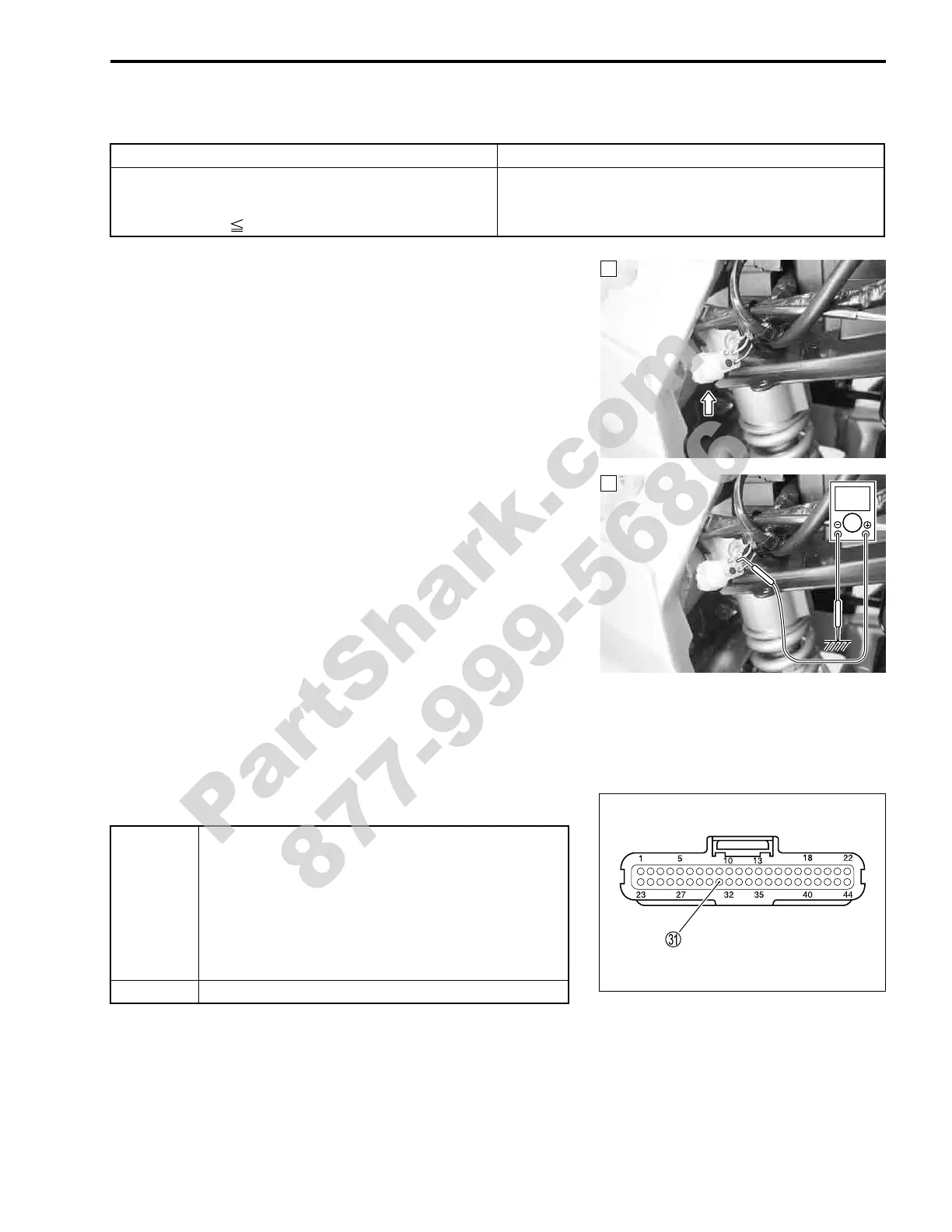
3) Check the GP switch coupler for loose or poor contacts.
If OK, then measure the GP switch voltage.
4) Support the motorcycle with a jack.
5) Turn the side-stand to up-right position.
6) Make sure the engine stop switch is in the “RUN” position.
7) Insert the needle pointed probes to the GP switch coupler.
8) Turn the ignition switch ON.
9) Measure the voltage at the wire side coupler between Pink
wire and ground, when shifting the gearshift lever from 1st to
Top.
% GP switch voltage: 1.0 V and more
(Pink – Ground)
! 09900-25008: Multi circuit tester set
09900-25009: Needle pointed probe set
' Tester knob indication: Voltage (()
Is the voltage OK?
DETECTED CONDITION POSSIBLE CAUSE
No Gear Position switch voltage
Switch voltage is out of the specified range.
Switch Voltage 0.2 V
• Gear Position switch circuit open or short.
• Gear Position switch malfunction.
• ECM malfunction.
1
1
V
YES
• Inspect the GP switch voltage. ("8-20)
• Pink wire open or shorted to ground, or poor
U
connection.
• If wire and connection are OK, intermittent trou-
ble or faulty ECM.
• Recheck each terminal and wire harness for
open circuit and poor connection.
NO Open or short circuit in the Pink wire.
PartShark.com
877-999-5686
 Loading...


