ELECTRICAL SYSTEM 8-23
IGNITION SYSTEM
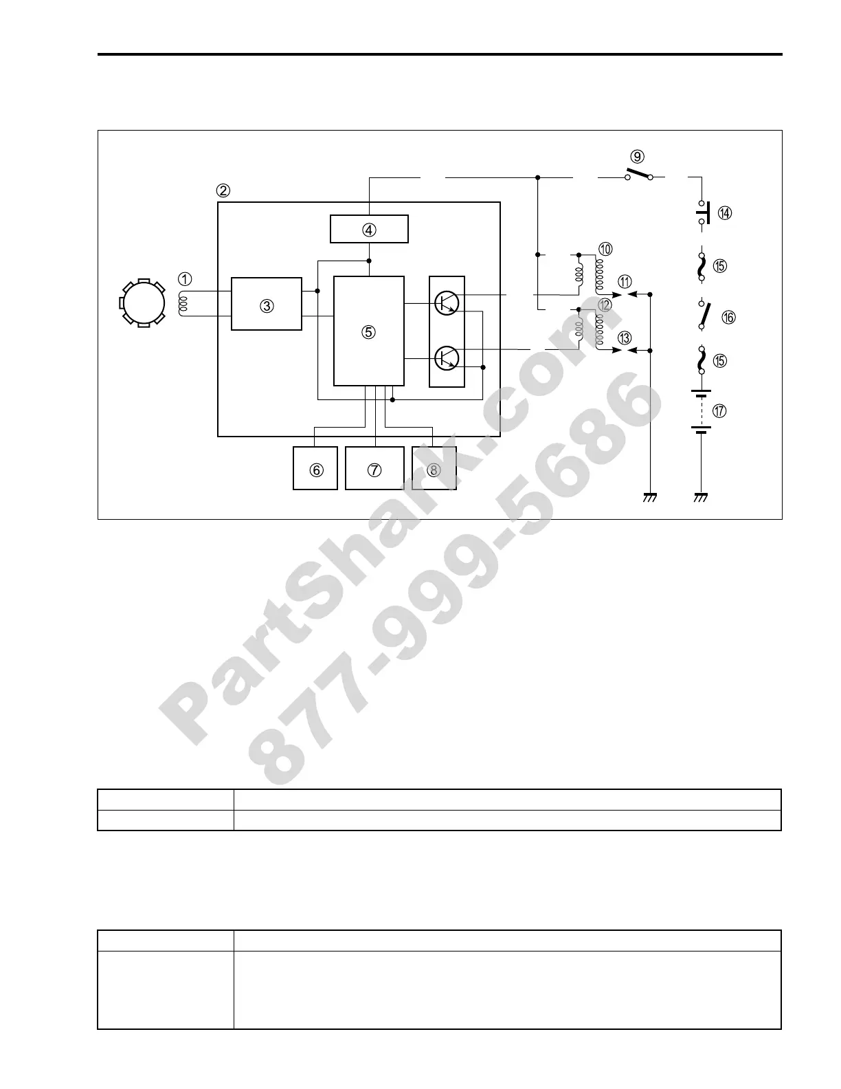
1 CKP sensor
2 ECM
3 Wave form arrangement circuit
4 Power source circuit
5 CPU
6 TP sensor
7 ECT sensor
8 Gear position switch
9 Engine stop switch
0 Ignition coil #1
A Spark plug #1
B Ignition coil #2
C Spark plug #2
D Side-stand relay
E Fuse
F Ignition switch
G Battery
TROUBLESHOOTING
No spark or poor spark
Make sure the engine stop switch is in the “RUN” position and side-stand is in up-right position. Make sure
the fuse is not blown and the battery is fully-charged before diagnosing.
Step1
1) Check the ignition system couplers for poor connections.
Is there connection in the ignition switch couplers?
Step 2
1) Measure the battery voltage between input lead wire (O/G and B/W) at the ECM with the ignition switch
in the “ON” position.
Is the voltage OK?
(10 A)
(30 A)
O
B/R
O/Y
O/BO/WO/G
W/Bl
O/W
B/O
B
YES Go to Step2.
NO Improper coupler connection.
YES Go to Step3.
NO
• Faulty ignition switch.
• Faulty turn signal/side-stand relay.
• Faulty engine stop switch.
• Broken wire harness or poor connection of related circuit couplers.
PartShark.com
877-999-5686
 Loading...


