April 2017
6-11
Xerox® VersaLink® B7025/B7030/B7035 Multifunction Printer
GP 8
General Procedures and Information
Launch Issue
GP 8 How to Check a Solenoid or Clutch
Purpose
Use this procedure to check a clutch or solenoid.
Initial Actions
WARNING
Ensure that the electricity to the machine is switched off while performing tasks that do
not need electricity. Refer to GP 10. Disconnect the power cord. Electricity can cause
death or injury. Moving parts can cause injury.
1. For a clutch, check that the mechanical components are clean, free to move and are lubri-
cated correctly.
2. For a solenoid, check that the armature and associated mechanical components are free
to move.
Procedure
NOTE: The voltages, PJ numbers, pin numbers and PWB names shown are an example only.
NOTE: When a solenoid is energized in diagnostics, armature movement is seen. When a
clutch is energized in diagnostics, the sound of the clutch action is heard. If possible, energize
the motor connected to the clutch to confirm when the clutch is energized.
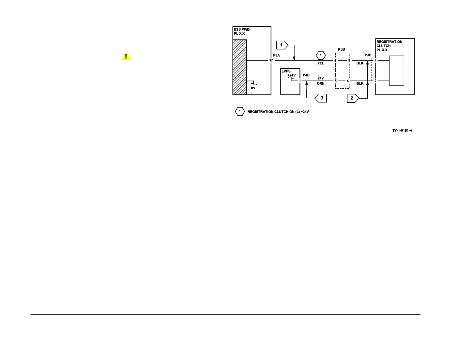
• Check that the signal changes on the ESS PWB (Flag 1) when the component control
code for the clutch or solenoid is entered.
• Disconnect PJC (Flag 2). Check that +24V is measured when the component control
code for the clutch or solenoid is entered.
• Disconnect PJD (Flag 3). Check for +24V on the LVPS.
• Check the wiring and the connectors for the clutch or solenoid circuit.
Figure 1 Wiring diagram
 Loading...