April 2017
2-100
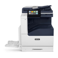
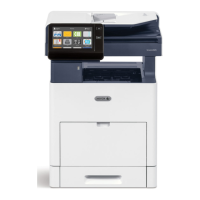
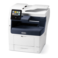
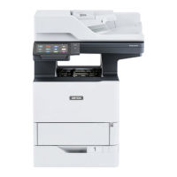
Xerox® VersaLink® B7025/B7030/B7035 Multifunction Printer
013-212, 013-213
Launch Issue
Status Indicator RAPs
013-212, 013-213 Booklet Staple Move Position Sensor Fail
RAP
BSD-ON: BSD 13.16 Office Finisher LX Booklet Staple Positioning
013-212 Booklet staple move position sensor does not actuate within designated time period.
013-213 Booklet staple move position sensor does not deactuate within designated time
period.
Initial Actions
WARNING
Ensure that the electricity to the machine is switched off while performing tasks that do
not need electricity. Refer to GP 10. Disconnect the power cord. Electricity can cause
death or injury. Moving parts can cause injury.
• Ensure the staple head is free from obstructions.
•Check dC122 Fault History for 013-306 or 013-307 faults. If either fault is listed, first per-
form the relevant procedure:
– 013-306 Booklet Safety Switches Open RAP.
– 013-307 Booklet Cover Open RAP.
Procedure
Enter dC330 code 013-144. Move the booklet stapler to actuate the booklet staple move posi-
tion sensor, PL PL 13.55 Item 13. The display changes.
YN
Check the wiring between J8898 pin 2 and P/J8991 pin 5 and between J8984 pin 5 and
J8985 pin 5 for an open or short circuit, or a loose or damaged connector.
The wiring is
good.
YN
Reconnect or repair as necessary.
Measure the voltage between P/J8991 pins 4 and 6 on the booklet PWB. The voltage is
approximately +5VDC.
YN
Install a new booklet PWB, PL 13.70 Item 4.
Measure the voltage between P/J8991 pin 5 on the booklet PWB and ground. Actuate
the booklet staple move position sensor.
The voltage changes.
YN
Install a new booklet staple move position sensor, PL 13.55 Item 13.
Measure the voltage between J8895 pin 5 on the finisher PWB and ground. Actuate the
booklet staple move position sensor.
The voltage changes.
YN
Install a new booklet PWB, PL 13.70 Item 4. If the fault persists, install a new finisher
PWB, PL 13.45 Item 2.
Install a new finisher PWB, PL 13.45 Item 2.
Enter dC330 code 013-028 and 013-029 alternately. The stapler move motor runs.
YN
Check the wiring between P/J8992 pins 1 to 6 on the booklet PWB and P/J8906 on the
booklet stapler move motor for an open or short circuit, or loose or damaged connectors.
The wiring is good.
YN
Reconnect or repair as necessary.
Monitor the voltage at J8984 pin 3. Enter dC330 code 013-028 and 013-029 alternately.
An AC clock pulse is detected.
YN
Check the wiring between J8984 pin 3 and J8985 pin 4. If the wiring is good, install
a new finisher PWB, PL 13.45 Item 2.
Install a new booklet stapler move motor, PL 13.55 Item 9. If the fault persists, install a
new booklet PWB, PL 13.70 Item 4.
Check the wiring for an intermittent fault.
A
A

 Loading...


