April 2017
4-89
Xerox® VersaLink® B7025/B7030/B7035 Multifunction Printer
REP 12.25
Repairs and Adjustments
Launch Issue
REP 12.25 Front /Rear Tamper Motor Assembly
Parts List on PL 12.26
Removal
WARNING
Switch off the electricity to the machine. Refer to GP 10. Disconnect the power cord
from the customer supply while performing tasks that do not need electricity. Electricity
can cause death or injury. Moving parts can cause injury.
1. Remove the compiler assembly, REP 12.19.
2. Remove the eject shaft assembly, REP 12.24.
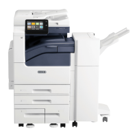
3. Remove the front/rear tamper motor assembly, Figure 1:
a. Remove two self-tapping screws (1).
b. Remove the screw (2).
c. Remove the front/rear tamper motor assembly (3).
Figure 1 Tamper motor assembly removal
Replacement
1. The replacement is the reverse of the removal procedure.
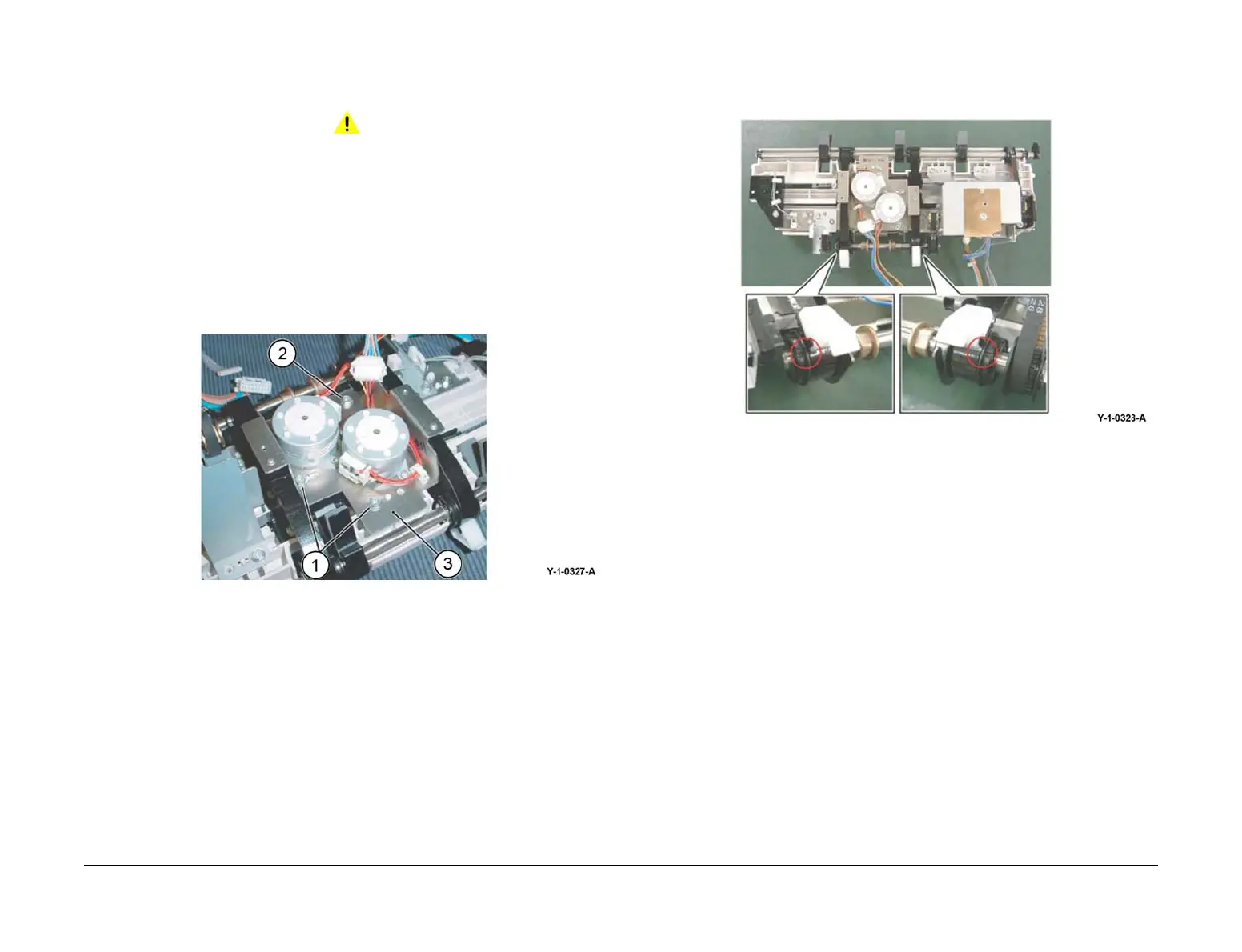
2. Ensure the eject belt is aligned with the marks on the pulleys, Figure 2.
Figure 2 Eject belt installation
 Loading...