114 Rockwell Automation Publication 1783-UM007G-EN-P - February 2017
Chapter 4 Install Stratix 5410 Switches
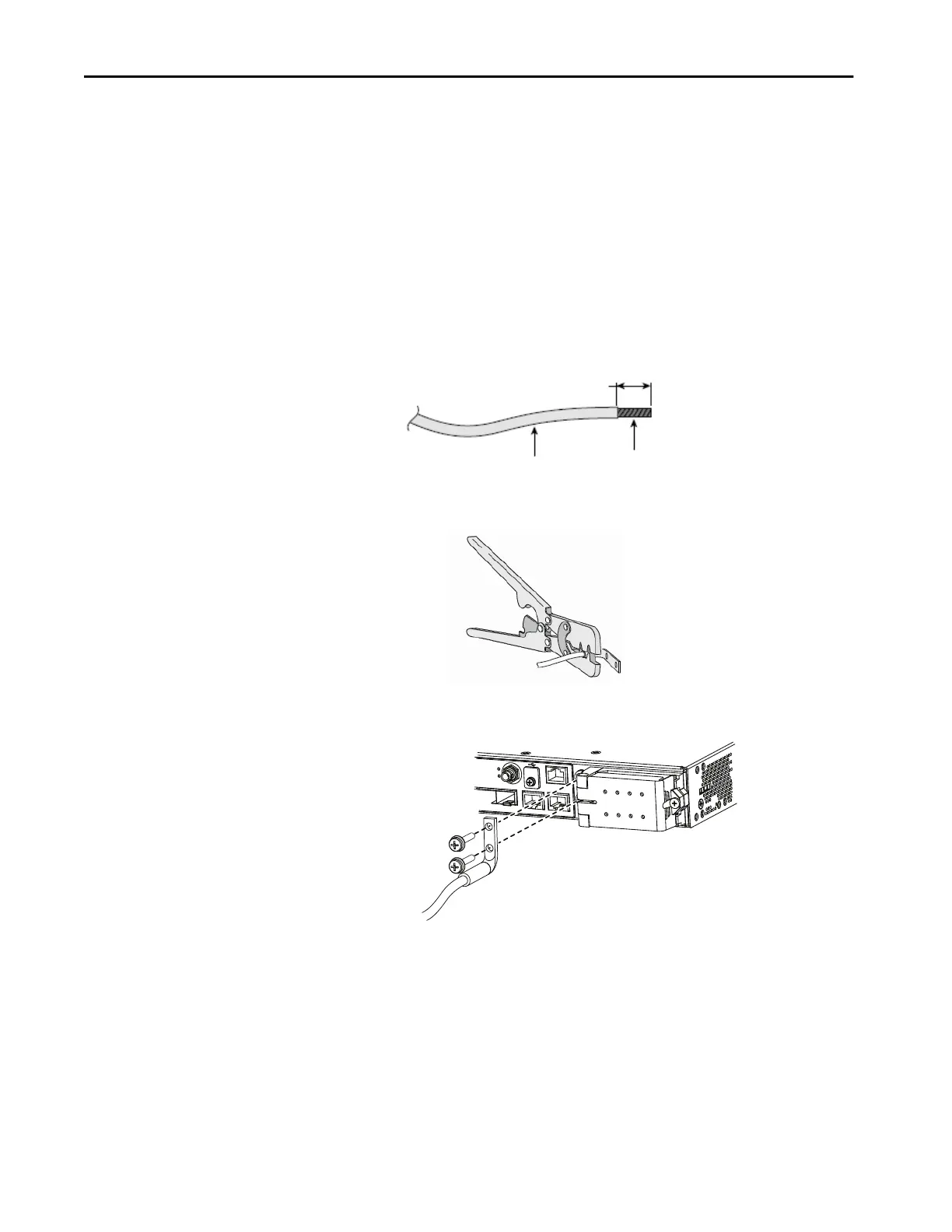
Ground the Switch
To ground the switch, follow these steps. Be sure to follow any grounding
requirements at your site.
1. To remove the ground screw from the cable side of the switch, use a
Phillips screwdriver or a ratcheting torque screwdriver with a Phillips
head.
Store the ground screw for later use.
2. Strip the 13.3 mm
2
(6 AWG) ground wire to 12.7 mm (0.5 in.) ± 0.5
mm (0.02 in.).
Stripping more than the recommended amount of wire can leave
exposed wire from the connector.
3. Insert the ground wire into the terminal lug, and crimp the terminal to
the wire.
4. Slide the ground screw from Step 1 through the terminal lug, and insert
the ground screws into the opening on the cable side.
5. Use a ratcheting-torque screwdriver to tighten the ground screws to
3.39 N•m (± 0.23 N•m) or 30 lb•in (± 2 lb•in).
6. Attach the other end of the ground wire to a grounded bare metal
surface, such as a ground bus or a grounded bare rack.
12.7 mm (0.5 in.) ± 0.5 mm (0.02 in.)
Insulation
Wire Lead
32560-M
Con
s
ole
28
ANA.TimeCode
Alarm
TOD
IN
O
U
Dual-hole Terminal Lug

 Loading...


