Rockwell Automation Publication 1783-UM007G-EN-P - February 2017 85
Install Stratix 5400 Switches Chapter 3
9. Connect the other end of the return wire to the return terminal on the
DC power source.
When you are testing the switch, one power connection is sufficient. If
you are installing the switch and are using a second power source, repeat
this procedure with the second power connector.
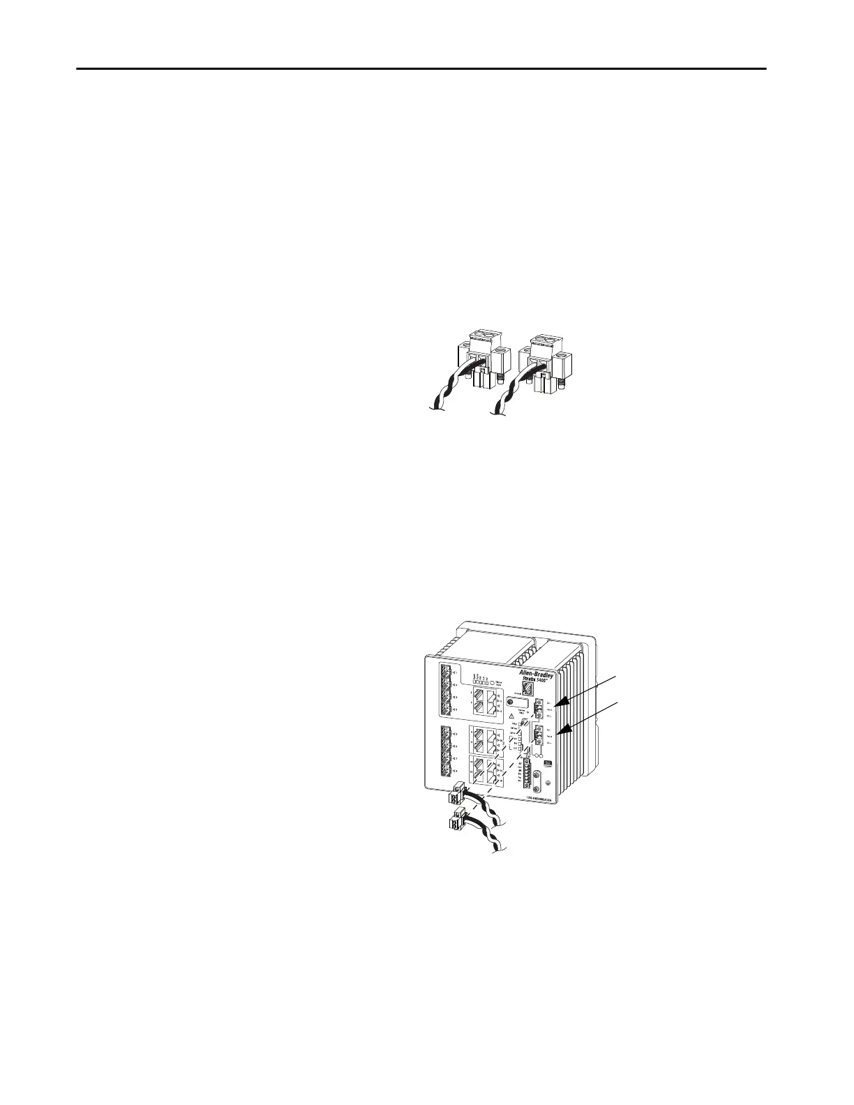
The following figure shows the completed DC input wiring on a power
connector for a primary power source and an optional secondary power
source.
Attach the Switch
Power Connectors
To attach the switch power connectors to the front panel of the switch, follow
these steps. There is no separate power connector for PoE.
1. Insert one power connector into the Pwr A receptacle on the switch
front panel, and the other into the Pwr B receptacle.
32282-M
32559-M
Pwr A Receptacle
Pwr B Receptacle

 Loading...


