Rockwell Automation Publication 1783-UM007G-EN-P - February 2017 213
Configure Switch Features Chapter 7
Overview
A DLR network is a single-fault-tolerant ring network that is intended for the
interconnection of automation devices without the need for more switches.
The ring topology offers these advantages:
• Media redundancy
• Fast-network fault detection and reconfiguration
• Resiliency of a single-fault-tolerant network
• Easy implementation without more hardware requirements
One DLR network can support as many as 50 nodes. A DLR network supports
copper connections (maximum of 100 m), fiber-optic connections (maximum
of 2 km), or a mix of copper and fiber.
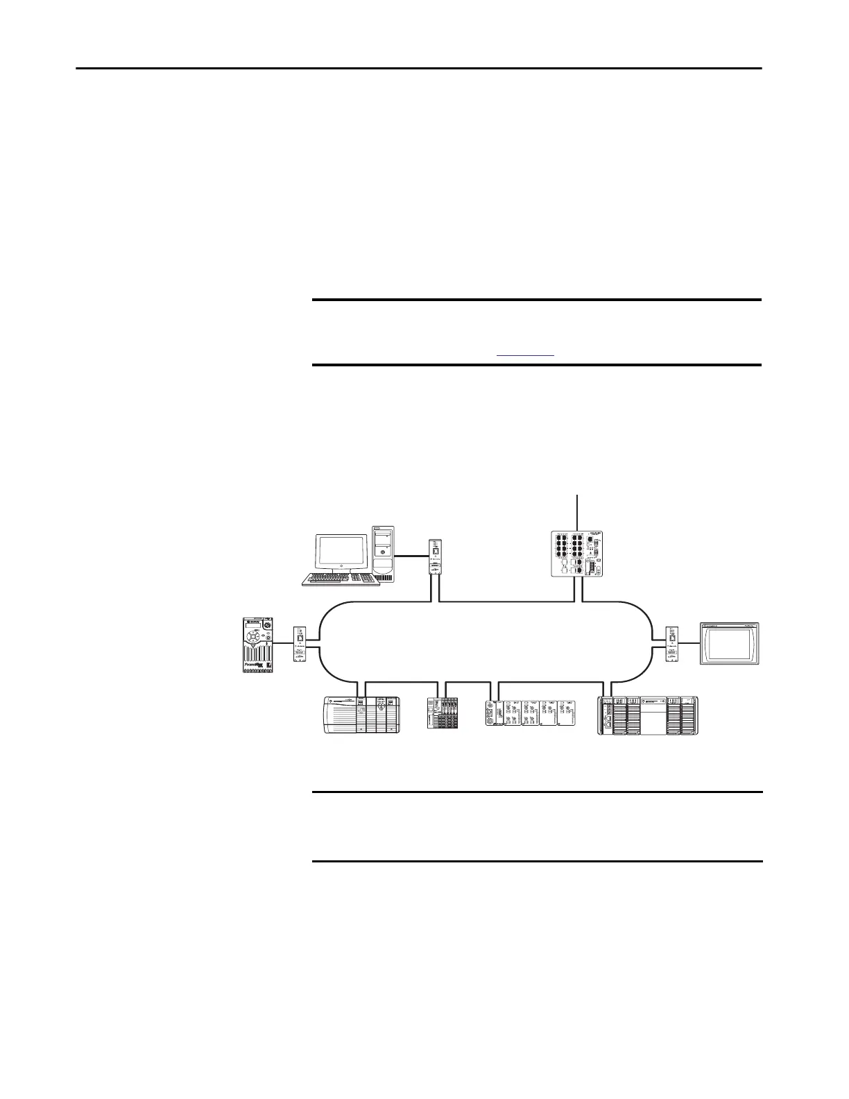
Figure 12 - Example Device-level Ring Topology
Figure 13 - A DLR network includes the following nodes.
IMPORTANT This section summarizes a DLR network. To plan, configure, and monitor
DLR networks, see EtherNet/IP Embedded Switch Technology Application
Guide, publication
ENET-AP005.
Com
IN2
Ref
IN1
Alarm
IN1 IN2 OUT
DC+
Pwr A
Express
Setup
Console
DC-
DC+
Pwr B
1783-ETAP
1783-ETAP
1783-ETAP
Stratix 5700 Switch
1756-EN2TR
1756 I/O Modules
1734-AENTR
1734 I/O Modules
1738-AENTR
1738 I/O Modules
1769-AENTR
1769 I/O Modules
To the Rest of the Network
PowerFlex® 525 Drive
IMPORTANT Stratix 5700 and ArmorStratix 5700 switches support only one ring per
switch.
Stratix 5400 switches support as many as three rings per switch.

 Loading...


