Rockwell Automation Publication 1783-UM007G-EN-P - February 2017 95
Install Stratix 5400 Switches Chapter 3
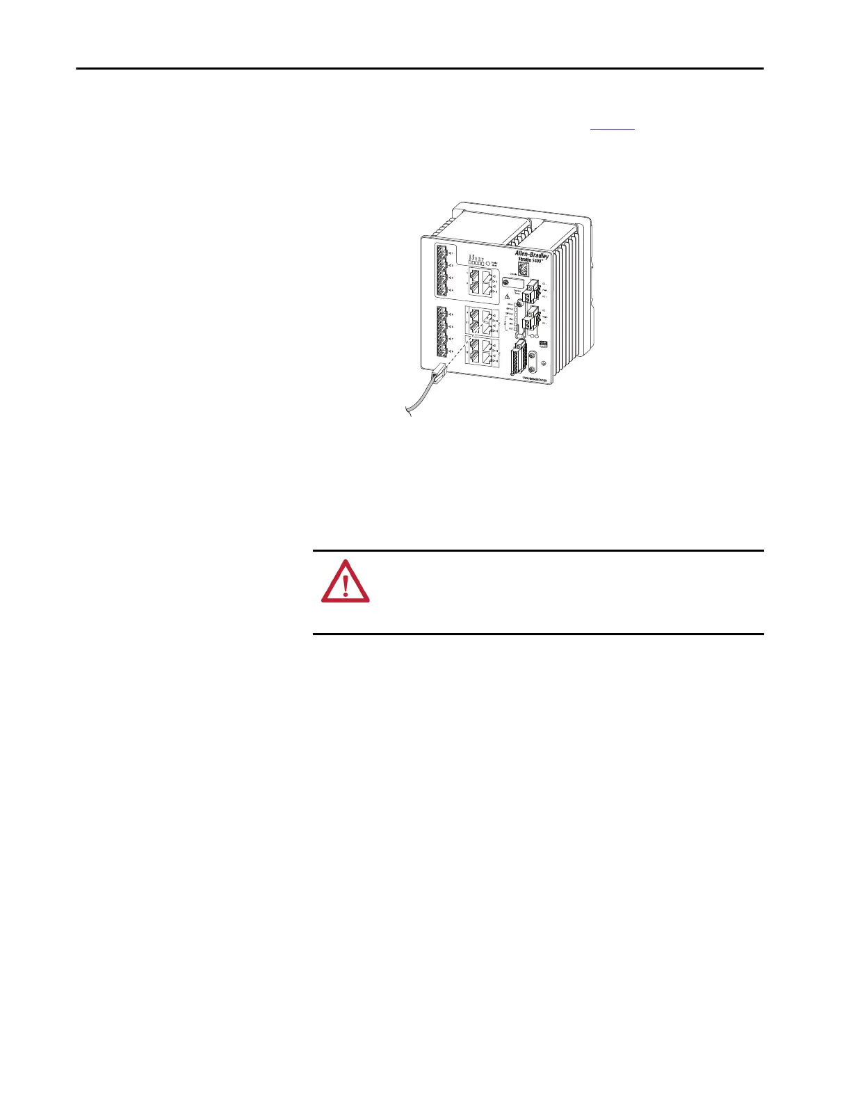
Connect to PoE Ports
Switches with PoE ports require a separate power supply. For power supply
requirements based on your application, refer to
page 83.
1. Insert a straight-through, twisted four-pair, Category 5e or better cable
with an RJ45 connector into the PoE port.
2. Insert the other cable end into an RJ45 connector on the other PoE
powered device.
Connect to SFP Module Ports
To connect a fiber-optic cable to an SFP module, follow these steps.
1. Remove the rubber plugs from the module port and fiber-optic cable,
and store them for future use.
2. Insert one end of the fiber-optic cable into the SFP module port.
3. Insert the other cable end into a fiber-optic receptacle on a target device.
4. Observe the port status indicator:
• The status indicator turns amber while the SFP discovers the
network topology and searches for loops. This process takes about 30
seconds, and then the port status indicator turns green.
• The status indicator turns green when the switch and the target
device have an established link.
• The status indicator turns off if the target device is not turned on or
there is a problem with the cable or the adapter that is installed in the
target device.
If necessary, reconfigure and restart the switch or the target device.
32565-M
ATTENTION: Do not remove the rubber plugs from the SFP module port or
the rubber caps from the fiber-optic cable until you are ready to connect the
cable. The plugs and caps protect the SFP module ports and cables from
contamination and ambient light.

 Loading...


