196 Rockwell Automation Publication 1783-UM007G-EN-P - February 2017
Chapter 7 Configure Switch Features
Before you configure a switch to use NTP-PTP clock mode, do the following:
• Configure NTP, as described on
page 295. While NTP-PTP Clock
mode requires only one NTP time source, as a best practice, we
recommend you configure two or more NTP time sources.
• Make sure the NTP clock is stable.
• Know the priority settings assigned to other PTP devices, so that you
can set up the switch as the grandmaster.
Configure Time Synchronization via Device Manager
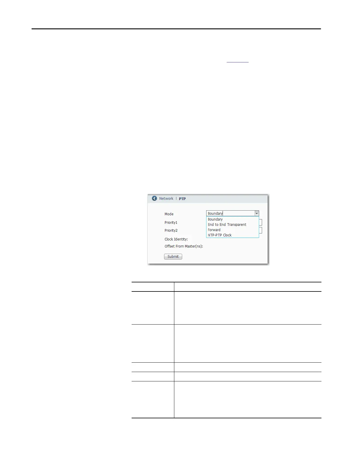
1. From the Configure menu, choose PTP.
2. From the Mode pull-down menu, choose a mode.
The modes and fields shown in the following figure vary based on the
switch model and mode setting.
3. Complete the following fields, and then click Submit.
Field Description
Priority 1 (Boundary or NTP-PTP Clock mode). Type a value to override the default criteria (clock
quality, clock class, and so on) for the best master clock selection. A lower value takes
precedence.
Valid values: 0…255
Default: 128
Priority 2 (Boundary or NTP-PTP Clock mode). Type a value to use as a tie-breaker between two
devices that are otherwise equally matched in the default criteria. For example, you can
give a specific switch priority over other identical switches. A lower value takes
precedence.
Valid values: 0…255
Default: 128
Clock Identity Displays a unique identifier for the clock.
Offset From Master (ns) Displays the time offset in nanoseconds between the slave and master clocks.
Passthrough
(Stratix 8000/8300
switches)
(Boundary or End to End Transparent mode). Check the checkbox to enable PTP pass-
through processing.
After PTP pass-through is enabled, all PTP messages are passed to and from the
expansion module ports in the VLAN on which the packets are received. The PTP pass-
through feature is not compatible with the Virtual Routing and Forwarding (VRF),
PolicyBased Routing (PBR), and PVLAN (Private Virtual Local Area Network) features.

 Loading...


