172 Rockwell Automation Publication 1783-UM007G-EN-P - February 2017
Chapter 6 Install Stratix 8000 and 8300 Switches
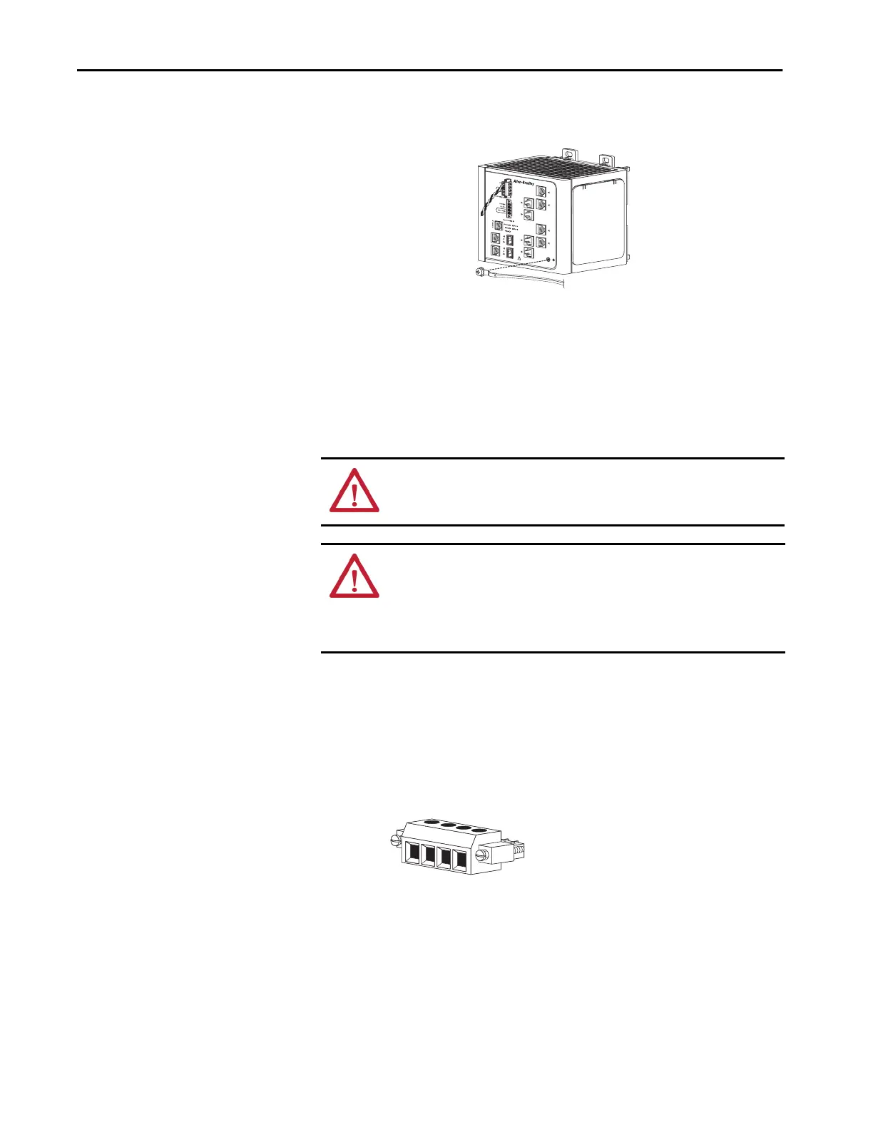
6. Insert the ground screw into the ground-screw opening on the front
panel.
7. Use a ratcheting torque screwdriver to tighten the ground screw and ring
terminal lug to the switch front panel to 0.96 N•m (8.5 lb•in).
8. Attach the other end of the ground wire to a grounded bare-metal
surface, such as a ground bus, or a grounded DIN rail.
Wire the DC Power Source
for the Switch
Follow these steps to wire DC power to the switch.
1. Locate the power and alarm relay connector and identify the positive
and return DC power connections.
The positive DC power connection is labeled V, and the negative DC
power connection is the adjacent connection labeled RT. Connections
labeled A are used for the alarm relay connectors.
2. Measure a length of 0.82…0.52 mm
2
(18…20 AWG) copper wire long
enough to connect to the DC power source.
VRTA A
31791-M
WARNING: Before performing any of the following procedures, make sure
that power is removed from the DC circuit or the area is nonhazardous before
proceeding.
WARNING: To comply with the CE Low Voltage Directive (LVD), this
equipment must be powered from a source compliant with the safety extra
low voltage (SELV) or protected extra low voltage (PELV).
To comply with UL restrictions, this equipment must be powered from a source
compliant with Class 2 or Limited Voltage/Current.
RT
A
V
A
31783-M

 Loading...


