Rockwell Automation Publication 1783-UM007G-EN-P - February 2017 145
Install Stratix 5700 Switches Chapter 5
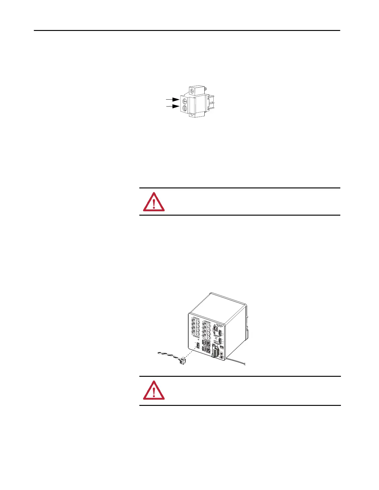
4. Insert the exposed part of the positive wire into the DC+ connection
and the exposed part of the return wire into the DC- connection.
Make sure that you cannot see any wire lead. Only wire with insulation
can extend from the connector.
5. Use a ratcheting-torque screwdriver to torque the captive screws of the
power connector to 0.23 N•m (2.0 lb•in).
6. Connect the other end of the positive wire (the one connected to DC+)
to the positive terminal on the DC power source.
7. Connect the other end of the return wire (the one connected to DC-) to
the return terminal on the DC power source.
Attach the PoE
Power Connector
This procedure applies only to switches with PoE ports.
1. Insert the power connector into the DC input terminal block on the
switch front panel.
2. Use a screwdriver to tighten the captive screws on the sides of the power
connector.
ATTENTION: If multiple power sources are used, do not exceed the specified
isolation voltage.
DC+
DC-
ATTENTION: Exposure to some chemicals can degrade the sealing properties
of materials used in the relay. Periodically inspect the relay and check for any
degradation.
PoE Input Pwr
48VDC, 1.2A

 Loading...


