532 Rockwell Automation Publication 1783-UM007G-EN-P - February 2017
Appendix D Cables and Connectors
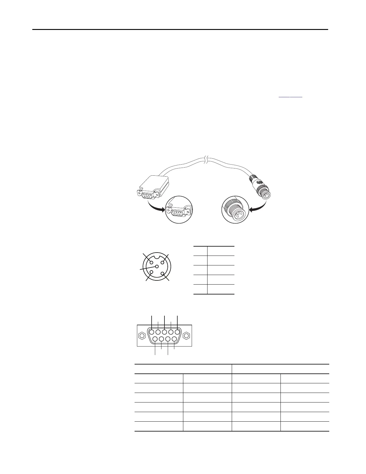
Console Port
ArmorStratix 5700 switches have one console port. The console port enables
you to connect the switch to a computer if you use the Command-line
interface (CLI) to configure and monitor the switch.
Connect to the console port with an M12-to-DB-9 cable (
Figure 82):
• Obtain a male 5-pin DC Micro-style (M12) connector configuration
cordset, such as Allen-Bradley Bulletin 889D.
• Obtain a DB-9 connector and attach it to one end of the cable.
Figure 82 - M12-to-DB-9 Cable
Figure 83 - Console Port Pinout
Figure 84 - DB-9 Connector Pinout
M8 Cable DB9-S Connector
Pin Function Pin Function
1RTS8CTS
2CTS7RTS
3TD2RD
4RD3TD
5 GRND 5 GRND
32552-M
4
5
3
1
2
1RTS
2CTS
3TXD
4RXD
5 GND
9876
9
8
7
6
54321
5
4
3
2
1
32499

 Loading...


