Rockwell Automation Publication 1783-UM007G-EN-P - February 2017 181
Install Stratix 8000 and 8300 Switches Chapter 6
Connect to Dual-purpose
Uplink Ports
The switches have two dual-purpose uplink ports. Each dual-purpose uplink
port has a 10/100/1000 RJ45 connector for a copper interface and a slot for an
SFP module. Only one port of the dual-purpose port can be active at a time. If
an SFP module port is connected, the SFP module port has priority.
Connect to 10/100/1000 Uplink Ports
1. Insert a straight-through, twisted four-pair, Category 5e or better cable
with an RJ45 connector into the port.
2. Insert the other cable end into an RJ45 connector on the other device.
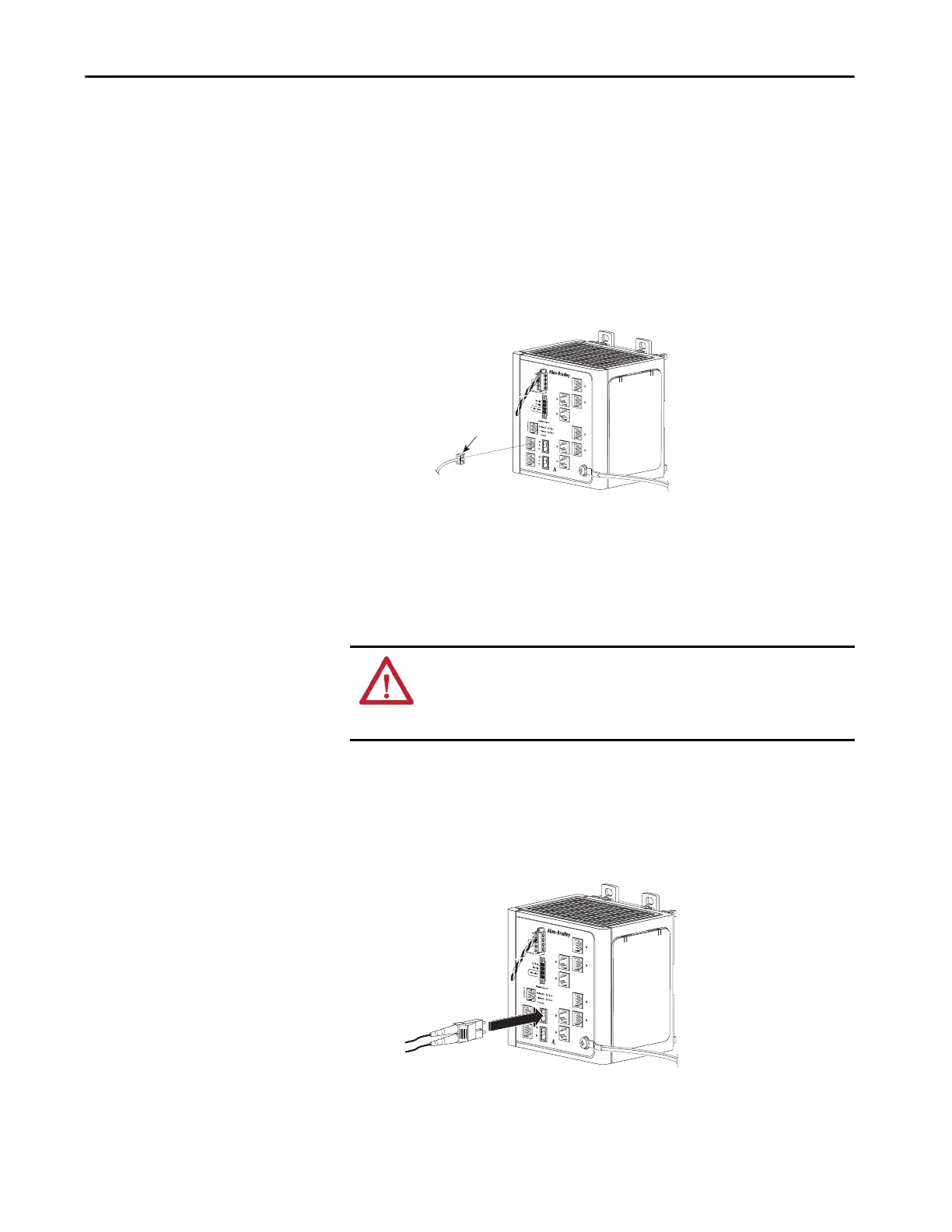
Connect to SFP Fiber Ports
Follow these steps if you installed an SFP module. For instructions on
installing, removing, and connecting to SFP modules, see the documentation
that shipped with the SFP module.
1. Insert a fiber-optic cable with an LC connector into the SFP fiber port.
2. Insert the other cable end into the other device.
ATTENTION: Class 1 laser product. Laser radiation is present when the small
form-factor pluggable (SFP) optical transceiver is open and interlocks
bypassed. Only trained and qualified personnel should be allowed to install,
replace, or service this equipment.
VRTAA
31795-M
To 10/100/1000 Ports
VRTA A
31796-M

 Loading...


