Rockwell Automation Publication 1783-UM007G-EN-P - February 2017 81
Install Stratix 5400 Switches Chapter 3
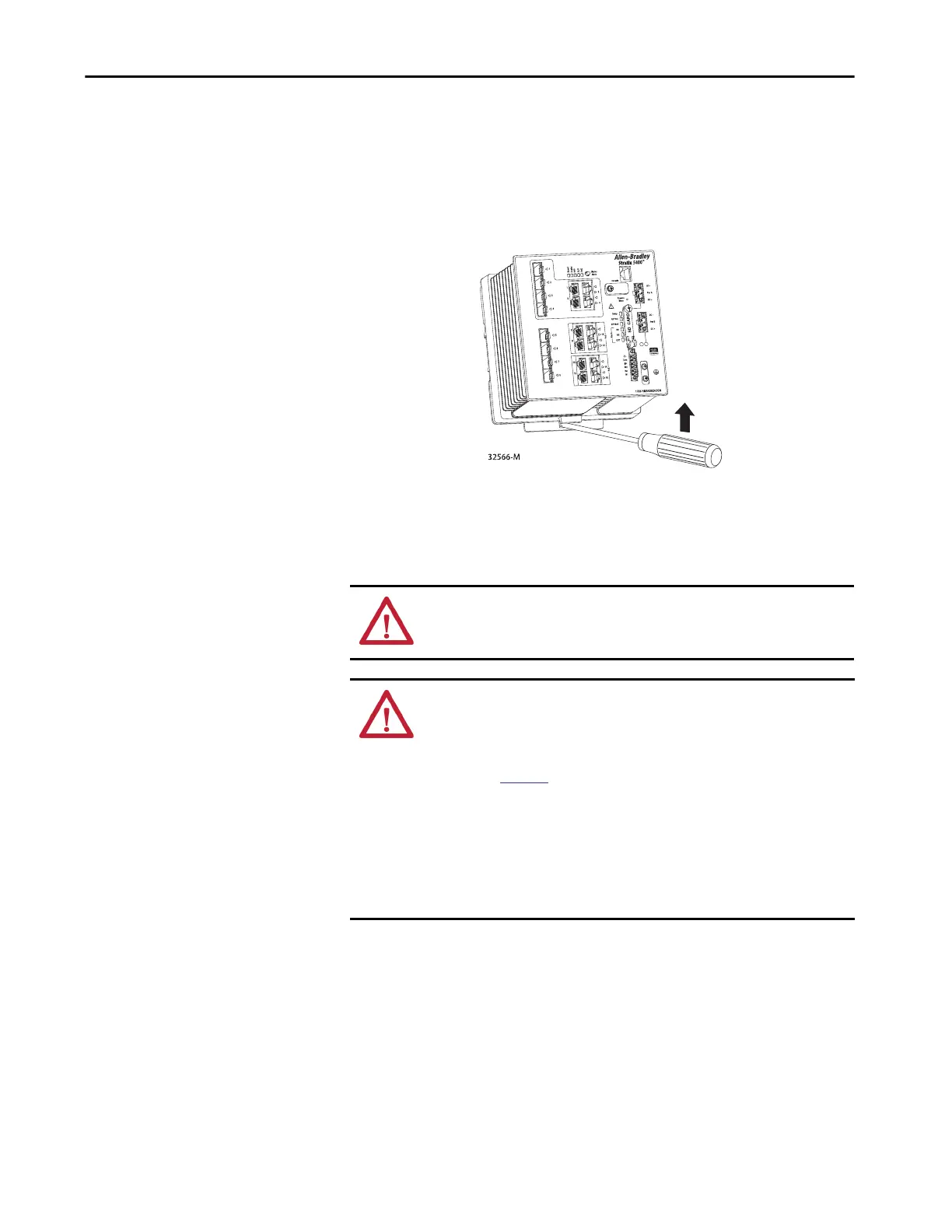
Remove the Switch
from the DIN Rail
To remove the switch from a DIN rail or a rack, follow these steps.
1. Remove power from the switch, and disconnect all cables and
connectors from the front panel of the switch.
2. Insert a tool, such as a flat-head screwdriver, in the slot at the bottom of
the spring-loaded latch and use it to release the latch from the DIN rail.
Ground the Switch
For DC power connections, use UL- and CSA-rated, style 1007 or 1569
twisted-pair copper appliance wiring material (AWM) wire.
Use at least 4 mm
2
(12 AWG) wire to connect to the external grounding screw.
The ground lug is not supplied with the switch. You can use one of the these
options:
• Single ring terminal
• Two single ring terminals
ATTENTION: To make sure that the equipment is reliably connected to earth
ground, follow the grounding procedure instructions and use a suitable ring
terminal lug, such as Thomas & Betts part number 10RCR or equivalent.
ATTENTION: For proper grounding, you must always connect the power
supply functional-ground screw when connecting the power supply. You
must provide an acceptable grounding path for each device in your
application. For more information on proper grounding guidelines, refer to
publication
1770-4.1, Industrial Automation Wiring and Grounding
Guidelines.
When using DIN rail mounting, additional grounding can also be accomplished
through the DIN rail. Use zinc-plated, yellow-chromate steel DIN rail to assure
proper grounding to an Earth Grounding path. Secure DIN rail to mounting
surface approximately every 200 mm (7.8 in.) using end-anchors appropriately
and using a washer plate along the entire length of the DIN rail.

 Loading...


