164 Rockwell Automation Publication 1783-UM007G-EN-P - February 2017
Chapter 6 Install Stratix 8000 and 8300 Switches
Attach Expansion Modules
The switch can operate as a standalone device with two uplink ports and four
or eight Fast Ethernet ports, or you can increase the number of Fast Ethernet
ports by 8 or 16 by connecting expansion modules.
You can install as many as two expansion modules per base unit. However, only
one of the two modules can be a 1783-MX08F or 1783-MX08S fiber
expansion module.
If you install a 1783-MX08F or 1783-MX08S fiber expansion module, the
module must be in the right-most position.
Depending on the mix of switches and expansion modules, you can have as
many 24 Fast Ethernet ports.
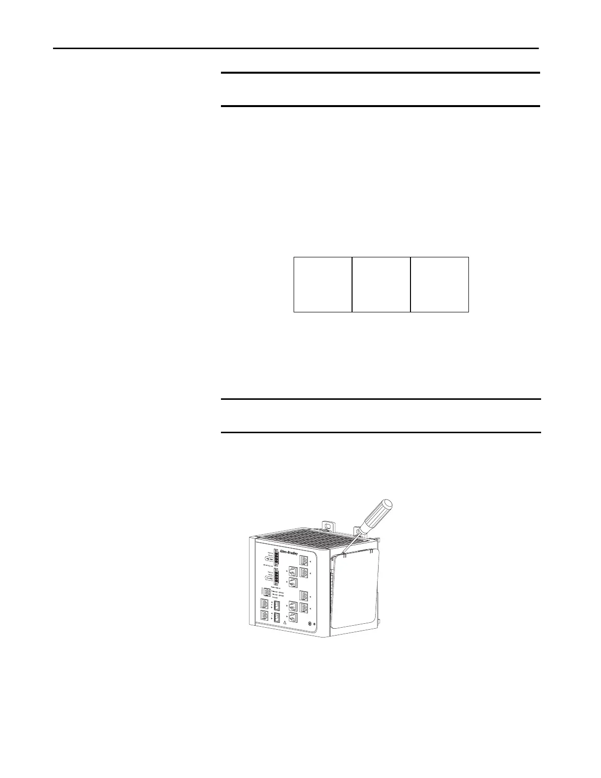
To connect the expansion modules to the switch, follow these steps.
1. Remove the right side panel by firmly grasping both sides of it in the
middle and pulling it outward.
If necessary, use a screwdriver to pry open the side panel.
IMPORTANT If you are adding expansion modules, attach the expansion modules to the
switch before mounting the switch.
IMPORTANT You must add expansion modules to the base unit before you apply power to
the switch. Remove power from the switch when reconfiguring it.
Base Unit
Expansion Module
1783-MX08F or
1783-MX08S
Expansion Module
31779-M

 Loading...


