Rockwell Automation Publication 1783-UM007G-EN-P - February 2017 535
Cables and Connectors Appendix D
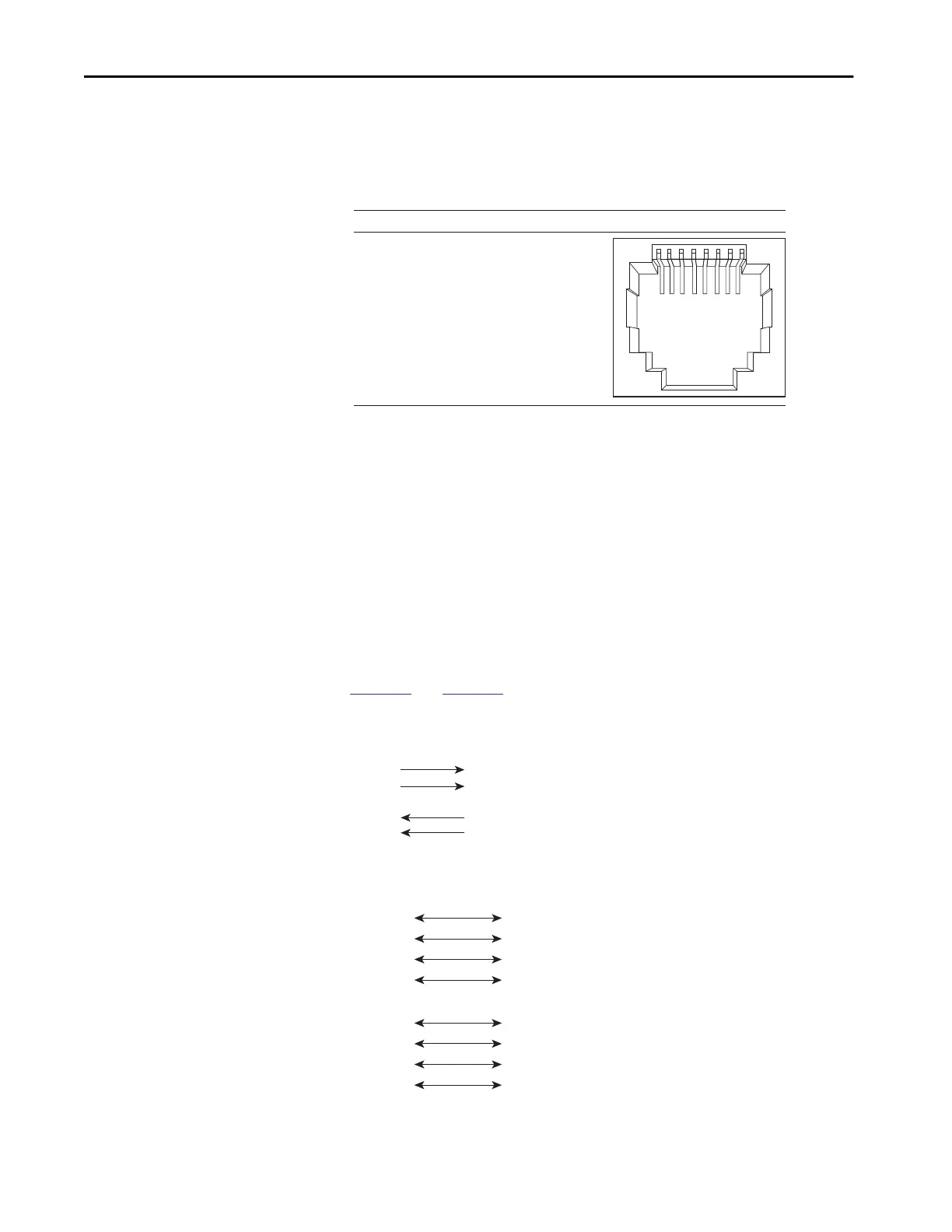
The PoE ports on the PoE expansion modules integrate power and data signals
on the same wires. The ports use standard RJ45 connectors and Ethernet
pinouts with internal crossovers.
Figure 89 - 10/100 PoE Connector Pinouts and Power Sourcing Equipment (PSE) Voltage
Connect to 10BASE-T- and 100BASE-TX-compatible Devices
When connecting the ports to 10BASE-T- and 100BASE-TX-compatible
devices, such as servers and routers, you can use a two or four twisted-pair,
straight-through cable that is wired for 10BASE-T and 100BASE-TX.
To identify a crossover cable, compare the two modular ends of the cable. Hold
the cable ends side-by-side, with the tab at the back. The color of the wire that
is connected to the pin on the outside of the left plug must differ in color from
the wire that is connected to the pin on the inside of the right plug.
Figure 90 and Figure 91 show the cable schematics.
Figure 90 - Two Twisted-pair Straight-through Cable Schematics
Figure 91 - Four Twisted-pair Straight-through Cable Schematics
23145678Pin Label Alternative A (MDI)
1
2
3
4
5
6
7
8
RD+ Positive V PSE
RD- Positive V PSE
TD+ Negative V PSE
NC
NC
TD- Negative V PSE
NC
NC
Switch
3 TD+
6 TD–
1 RD+
2 RD–
Router or Personal Computer
3 RD+
6 RD–
1 TD+
2 TD–
1 TPO+
2 TPO-
3 TP1+
6 TP1-
1 TP1+
Switch Router or Personal Computer
2 TP1-
3 TPO+
6 TPO-
4 TP2+
5 TP2-
7 TP3+
8 TP3-
4 TP3+
5 TP3-
7 TP2+
8 TP2-

 Loading...


