528 Rockwell Automation Publication 1783-UM007G-EN-P - February 2017
Appendix D Cables and Connectors
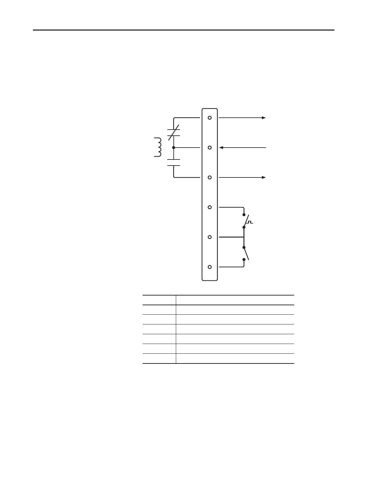
Alarm Ports
The front-panel alarm-relay connector ports are described in the following
illustration and table.
Figure 75 - Wiring Example for Alarm Inputs and Outputs
PoE Port Cable Specifications
For PoE ports, use a Category 5 (Cat 5) cable with a distance of up to 100 m
(328 ft).
Alarm
Relay
Coil
Alarm Input 2
Alarm Input 1
User-supplied contact closure
generates external alarms.
1
2
3
4
5
6
To Alarm Input
+24V DC from User
To Alarm Input
Alarms Connector
NO
COM
NC
IN2
REF
IN1
Label Connection
NO Alarm Output Normally Open (NO) connection
COM Alarm Output Common connection
NC Alarm Output Normally Closed (NC) connection
IN2 Alarm Input 2
REF Alarm Input Reference Ground connection
IN1 Alarm Input 1

 Loading...


