146 HD96-24-CC-TP User Manual
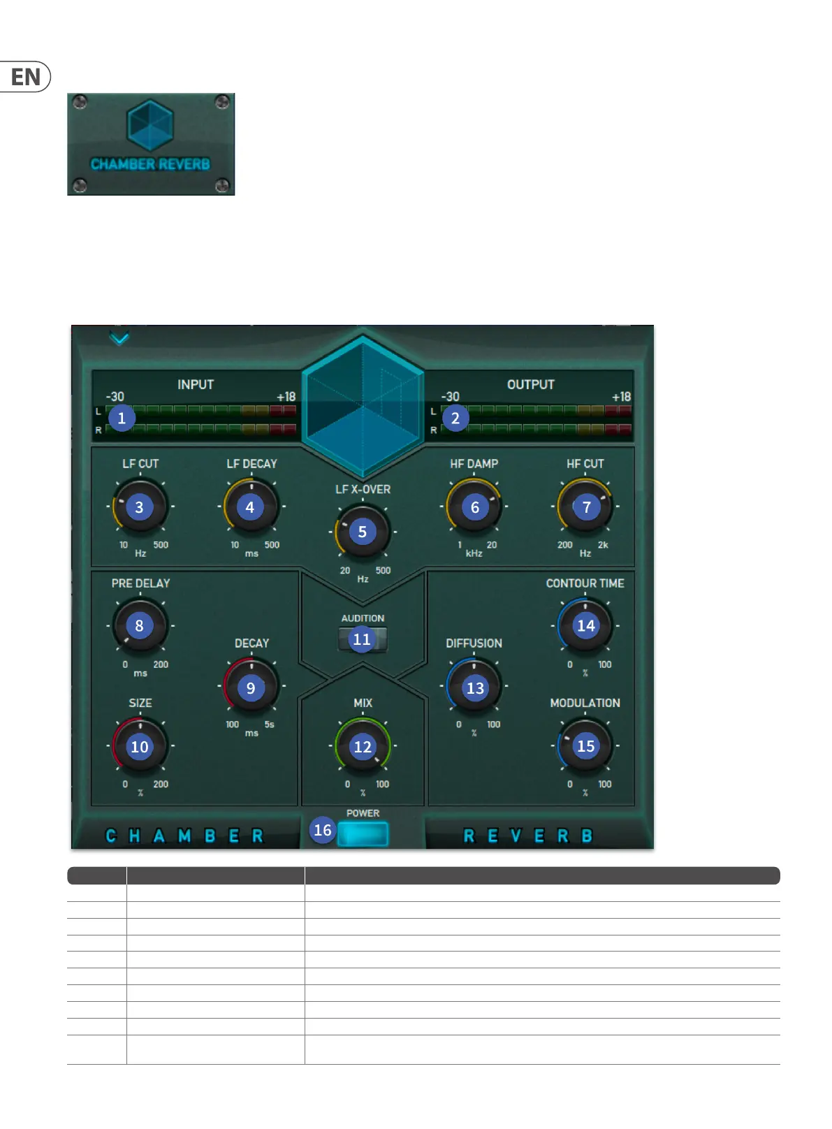
Chamber Reverb
The chamber reverb emulates the sound of echo chambers found in early recording studios. This is characterized by a rapid buildup of reection density within a small
to medium sized space coupled with a relatively colorless and smooth decay.
Reective surface materials and air absorption properties can be simulated by adjusting the high and low frequency cut amount and high frequency damping. Low
frequency decay and cross-over parameters allow relative control over the low band reverb tail length. This can be used to either simulate real room responses, which
often have a longer decay time at low frequencies, or alternatively can be useful to reduce low frequency energy in a live environment where it may already be present
due to the natural reverberation of the venue.
Item Control Function
1 INPUT Level meter LED Metering shows input level.
2 OUTPUT Level meter LED Metering shows output level.
3 LF Cut control Control that adjusts the Low Frequency cut from 10 Hz to 500 Hz.
4 LF Decay Adjusts the length of the low frequency section of the reverb in compression to the rest of the reverb tail.
5 LF X-over Changes the X-Over point of the reverb from 20 Hz to 500 Hz.
6 HF Damp Dampens the HF to produce a darker sounding reverb. Settings from 1 kHz to 20 kHz.
7 HF Cut control Control that adjusts the High Frequency cut from 0.2 kHz to 20 kHz.
8 Pre Delay control Controls the amount of delay (in milliseconds) between the initial signal and the onset of reverberation.
9 Decay control Control that sets the overall (mid-band) reverberation decay time. Range is from 0.5 to 10 seconds, depending on room size.
10 Size control
Adjusts the average dimension of the simulated space. Range is from 0% to 100% of the largest space possible. A momentary
mute is implemented when this control is adjusted.
 Loading...