32 HD96-24-CC-TP User Manual
The assignable controls above the faders and to the side of the GUI can be fully customised to suit your workow. Functions can be changed quickly with the cursor
arrow controls. For e.g. altering pan position, aux control or gain changes.
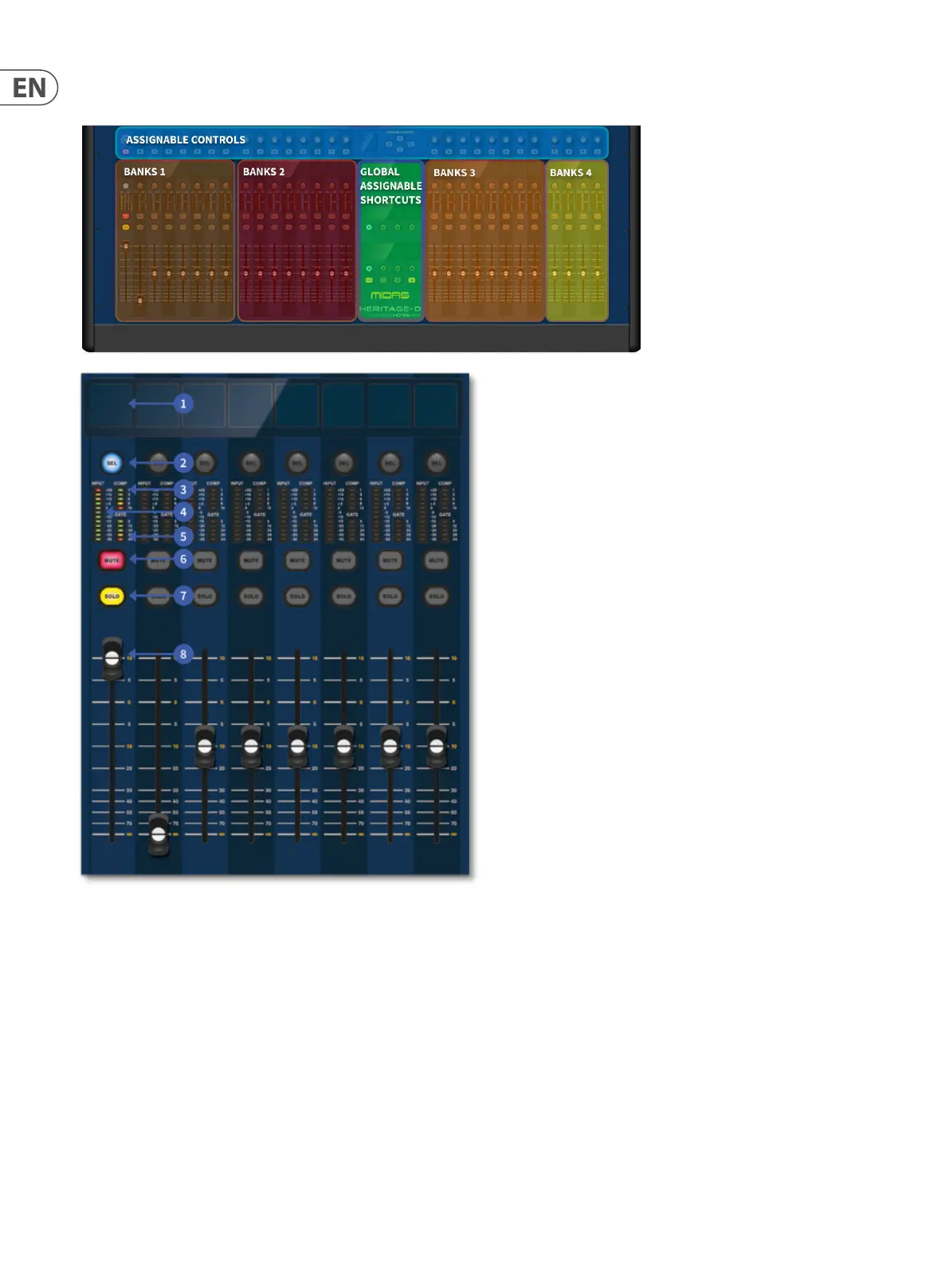
Channel strip layout
Each channel strip within a bank provides:
1 – LCD DISPLAY - A high-resolution display providing metering, channel information and ip status.
and local parameter values.
2 – SEL - Selects the channel for a variety of operations, including adjusting parameters
from the GUI and assigning to the channel detail area.
3 – COMP - Compressor gain reduction meter.
4 – INPUT - Input metering.
5 – GATE - Gate gain attenuation met,er.
6 – MUTE - Press the MUTE button to mute the channel.
7 – SOLO - Press SOLO to listen to the channel signal
8 – LEVEL - The fader is touch sensitive providing level control from ∞ to +10 dB (or +6 dB if contributing to an output bus)
 Loading...