185 HD96-24-CC-TP User Manual
Tape Saturation
As its name suggests, the Tape Saturation eect emulates analogue tape saturation; when the number of magnetised particles required to fully record and reproduce
an audio signal exceeds the amount available. This can be heard as analogue ‘warmth’, and similar eects can be achieved in the digital domain by emulating various
analogue tape artefacts.
An example of this is tape’s tendency to compress the high frequencies in ‘transients’, or peaks in the audio signal, and while this is a side-eect of using analogue
tape, it can also be desirable when trying to achieve a vintage tape sound. This eect can be altered by use of the Transient Smoothing control. Another way to achieve
that nostalgic tape sound is by the creative use of biasing; most professional tape machines are set up to compensate for this, in other words, to be slightly overbiased.
The Overbias control is used to emulate this by reducing the amount of tape distortion at the expense of the high frequencies and transients. The limit of the high
frequency response is also controlled by the overall frequency response of the tape process, and this in turn is aected mainly by utilising dierent tape speeds. Slower
tape speeds 3¼ or 7½ ips) have less high frequency denition and a boost at low and mid frequencies, whereas higher speeds (15 / 30 ips) have better high frequency
representation and less extreme lower ends resulting in more accurate audio reproduction.
Another important element to tape emulation is the output transformer which supplies a low end ‘bump’ in the frequency response and increases harmonic distortion
of frequencies between approximately 50 – 100 Hz. The amount of distortion can be controlled by eective use of the Transformation control.
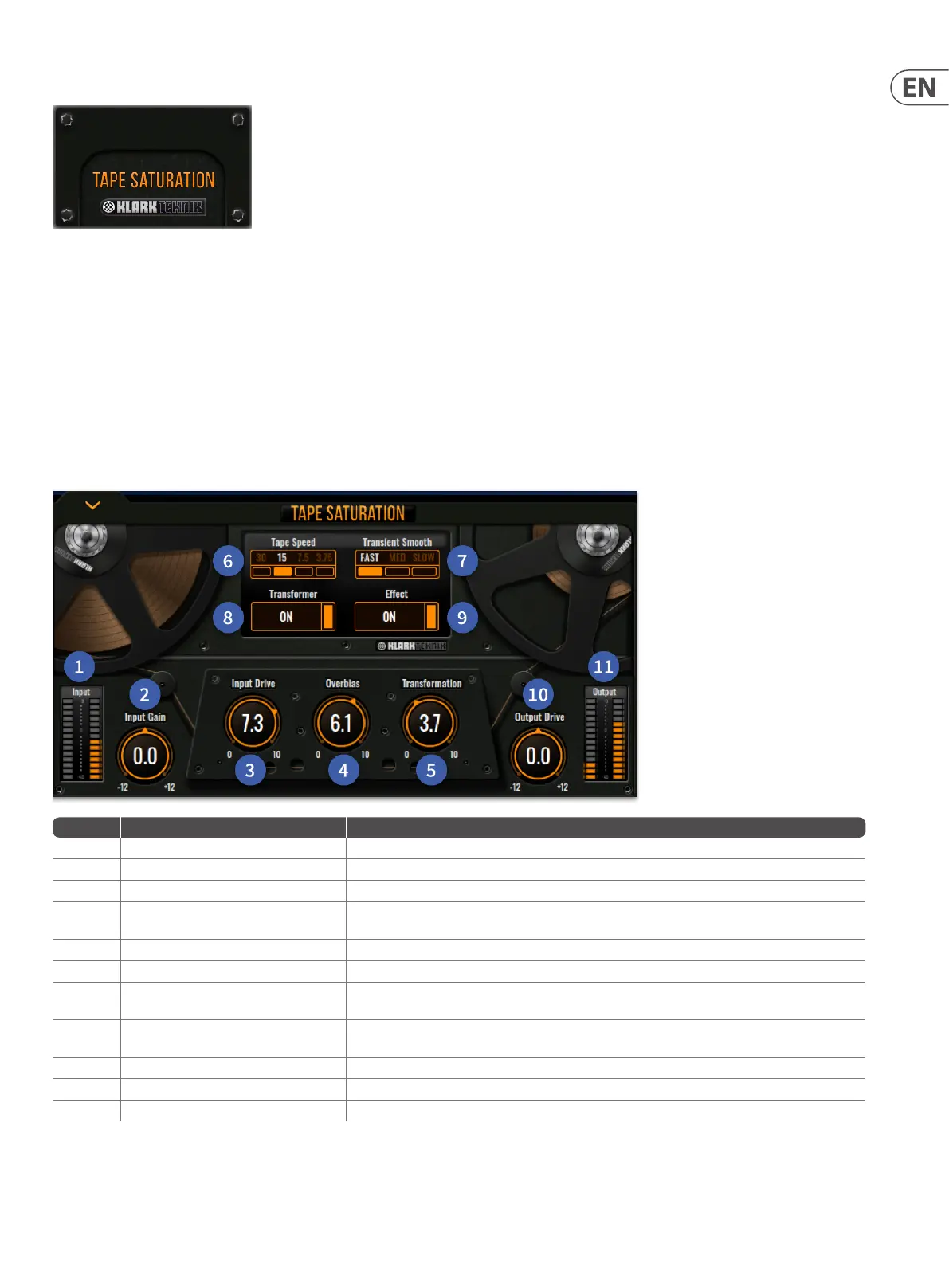
Item Control Function
1 Input meter 14 LEDs, which show input metering.
2 Input Gain control Sets the level into the tape machine.
3 Input Drive control Increases the eect of tape saturation applied.
4 Over bias control
Over bias is used to emulate nostalgic tape sound. The Over bias control is used to emulate this by
reducing the amount of tape distortion at the expense of the high frequencies and transients
5 Transformation control The amount of transformer drive applied. 1-10 Range.
6 Tap Speed button Changes the tape speed. 3¼, 7½, 15 or 30 ips.
7 Transient Smooth button
Changes the speed in which Transients are handled to compress the high frequencies in a subtle
way. Fast, Med or Slow options.
8 Transformer button
The output transformer supplies a low end ‘bump’ in the frequency response and increases
harmonic distortion of frequencies between approximately 50 – 100 Hz.
9 Eect button Toggles the eect on/o.
10 Output Drive control Sets the output level from -12 to +12 with 0 at top dead centre
11 Output Meter 14 LEDs, which show output metering.
 Loading...