3D Graphing 383
By displaying and labeling the axes, you can more easily see the pattern in the cursor
movement. To move grid points closer together, you can increase Window variables
xgrid and ygrid.
When the trace cursor is on an interior point in the displayed plane, the cursor moves
from one grid point to the next along one of the grid wires. You cannot move diagonally
across the grid. Notice that the grid wires may not appear parallel to the axes.
Example of the Cursor on a Hidden Surface
Example of the Cursor on a Hidden SurfaceExample of the Cursor on a Hidden Surface
Example of the Cursor on a Hidden Surface
On more complex shapes, the cursor may appear as if it is not on a grid point. This is an
optical illusion caused when the cursor is on a hidden surface.
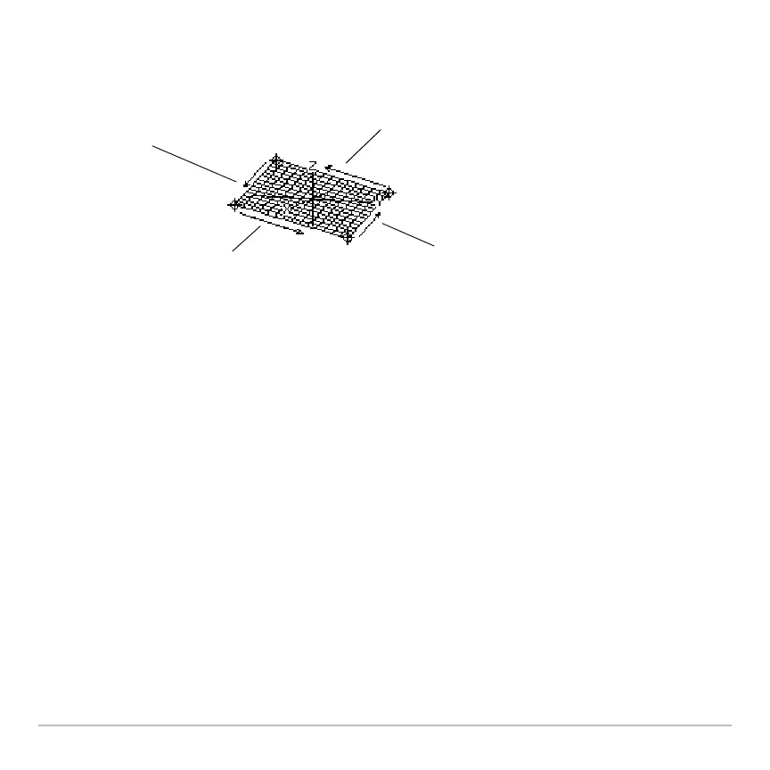
D moves in a negative
y direction, back to ymin.
B moves in a positive
x direction, up to xmax.
A moves in a negative
x direction, back to xmin.
C moves in a positive
y direction, up to ymax.
When you press …, the trace cursor appears
at the midpoint of the xy grid. Use the cursor
pad to move the cursor to any edge.
 Loading...