3D Graphing 393
– or -
8
F
To change any of these settings, use the same procedure that you use to change other
types of dialog boxes, such as the MODE dialog box.
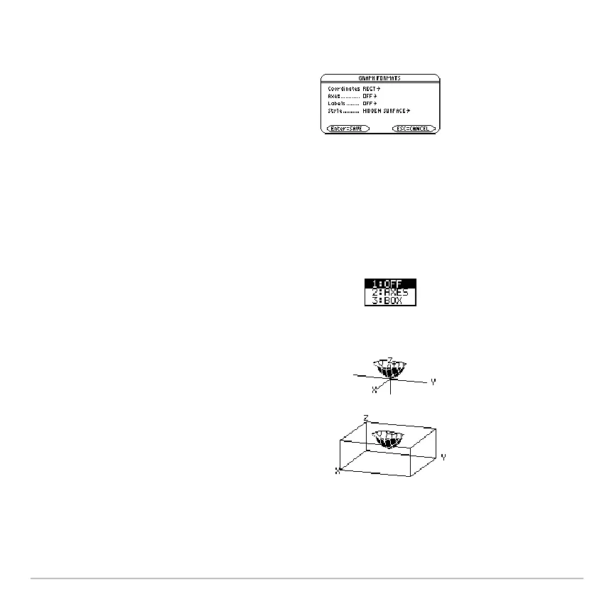
Examples of Axes Settings
Examples of Axes SettingsExamples of Axes Settings
Examples of Axes Settings
In many cases, the origin (0,0,0) is inside the box, not at a corner. For example, if
xmin = ymin = zmin = L10 and xmax = ymax = zmax = 10, the origin is at the center of
the box.
• The dialog box shows the current graph
format settings.
• To exit without making a change, press
N.
To display the valid
Axes settings, highlight
the current setting and press B.
• AXES — Shows standard xyz axes.
• BOX — Shows 3-dimensional box axes.
The edges of the box are determined by
the Window variables
xmin, xmax, etc.
z1(x,y) = x
2
+.5y
2
 Loading...