Configuring Spanning Tree Parameters Spanning Tree Operating Modes
OmniSwitch AOS Release 8 Network Configuration Guide December 2017 page 6-22
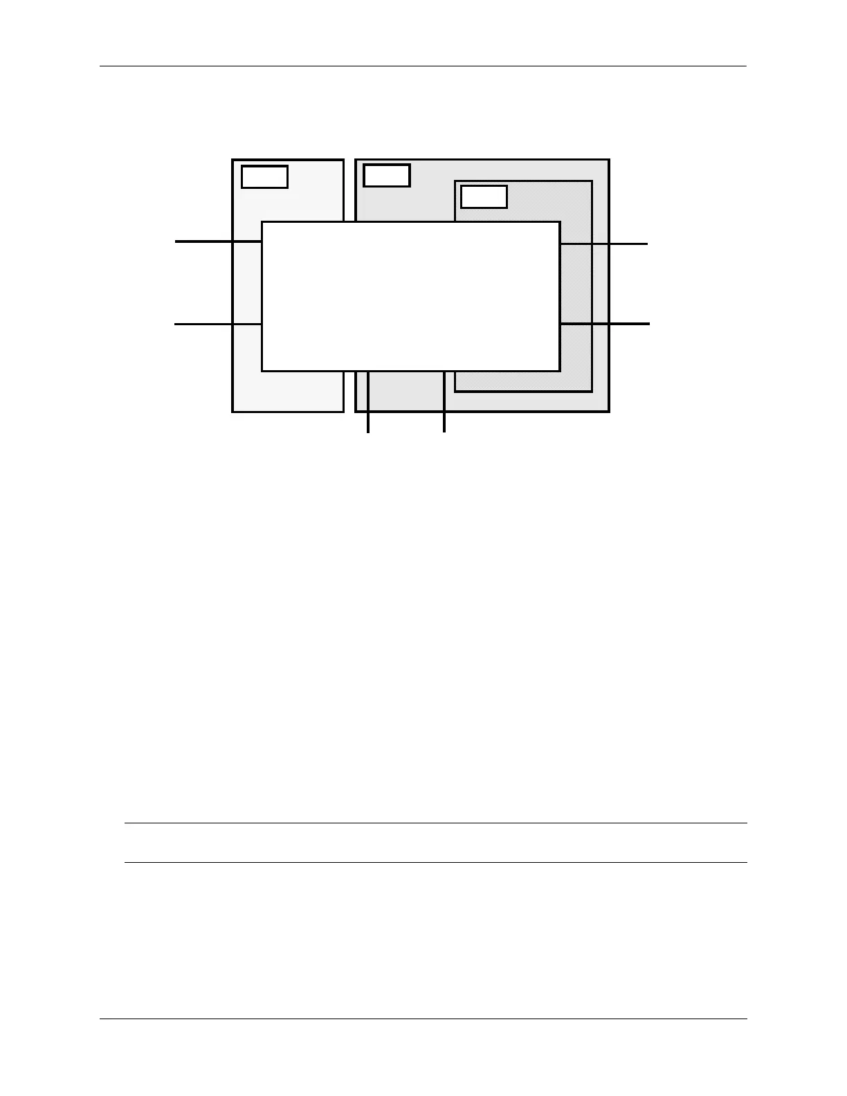
The following diagram shows a switch running in the per-VLAN Spanning Tree mode and shows
Spanning Tree participation for both fixed and tagged ports.
Per VLAN (single and 802.1Q) Spanning Tree Example
In the above example, STP2 is a single Spanning Tree instance since VLAN 5 contains only fixed ports.
STP 3 and STP 4 are a combination of single and 802.1Q Spanning Tree instances because VLAN 2
contains both fixed and tagged ports. On ports where VLAN 2 is the default VLAN, BPDU are not tagged.
on ports where VLAN 2 is a tagged VLAN, BPDU are also tagged.
Using Per-VLAN Spanning Tree Mode with PVST+
In order to interoperate with Cisco's proprietary Per Vlan Spanning Tree (PVST+) mode, the OmniSwitch
per-VLAN Spanning Tree mode allows OmniSwitch ports to transmit and receive either the standard
IEEE BPDUs or Cisco's proprietary PVST+ BPDUs. When the PVST+ mode is enabled, a user port
operates in the default mode initially until it detects a PVST+ BPDU, which automatically enables the port
to operate in the Cisco PVST+ compatible mode.
The PVST+ compatibility mode allows OmniSwitch ports to operate in the per-VLAN mode when
connected to another OmniSwitch or in the Cisco PVST+ mode when connected to a Cisco switch. As a
result, both the OmniSwitch per-VLAN and Cisco PVST+ modes can co-exist on the same OmniSwitch
and interoperate correctly with a Cisco switch using the standard Spanning Tree protocols (STP or RSTP).
Note. In the flat Spanning Tree mode, both the OmniSwitch and Cisco switches can interoperate seamlessly
using the standard MSTP protocol.
STP 2
STP 3
STP 4
Switch
Port 1/5
Default VLAN 10
VLAN 2 (tagged)
Port 2/5
Default VLAN 2
VLAN 10 (tagged)
Port 2/4
Default VLAN 2
Port 2/3
Default VLAN 5
Port 1/3
Default VLAN 5
Port 1/4
Default VLAN 2
 Loading...