Configuring Spanning Tree Parameters Sample MSTI Configuration
OmniSwitch AOS Release 8 Network Configuration Guide December 2017 page 6-48
Sample MSTI Configuration
By default, the Spanning Tree software is active on all switches and operating in the per-VLAN mode
using 802.1w RSTP. A loop-free network topology is automatically calculated based on default 802.1w
RSTP switch, bridge, and port parameter values.
Using Multiple Spanning Tree (MST) requires configuration changes to the default Spanning Tree values
(mode and protocol) as well as defining specific MSTP parameters and instances.
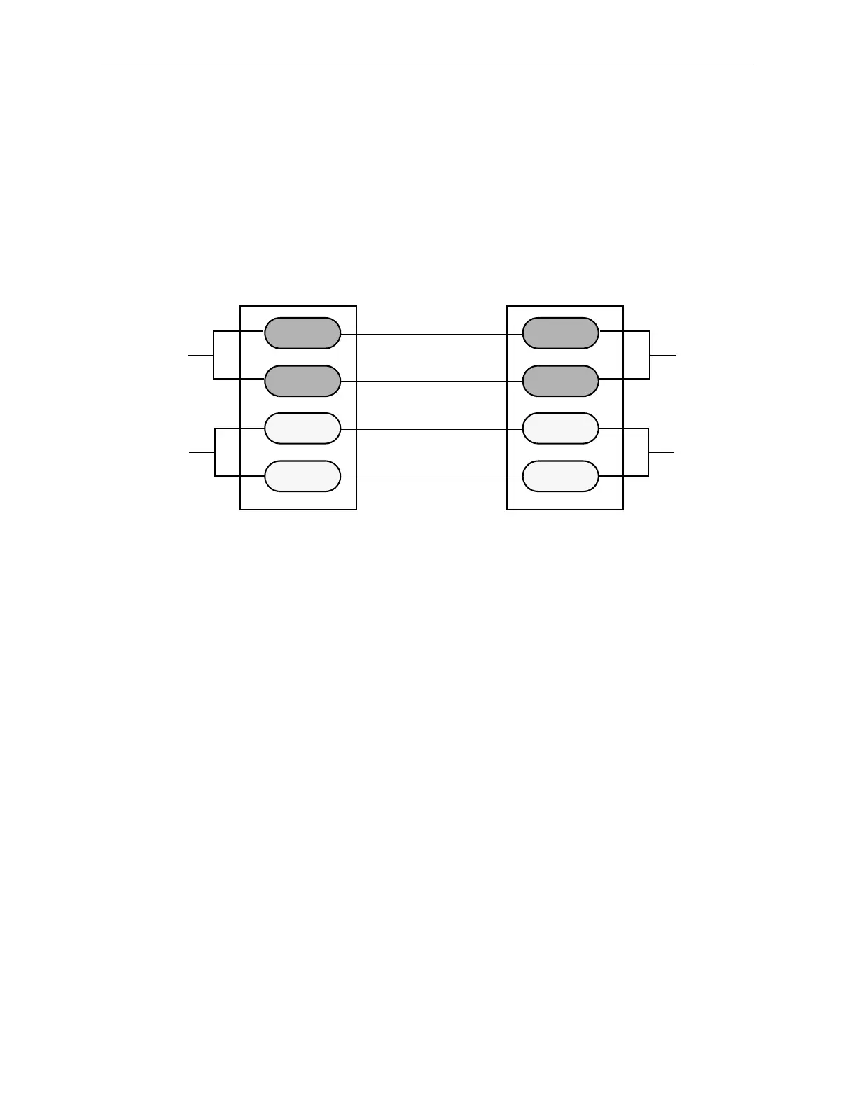
The following steps provide a tutorial for setting up a sample MSTP configuration, as shown in the
diagram below:
Flat Mode MSTP Quick Steps Example
1 Change the Spanning Tree operating mode, if necessary, on Switch A and Switch B from per-VLAN to
flat mode using the spantree mode command. For example:
-> spantree mode flat
Note that defining an MSTP configuration requires the use of explicit Spanning Tree commands,
which are available in both the flat and per-VLAN mode. As a result, this step is optional. See “Using
Spanning Tree Configuration Commands” on page 6-26 for more information.
2 Change the Spanning Tree protocol to MSTP using the spantree protocol command. For example:
-> spantree protocol mstp
3 Create VLANs 100, 200, 300, and 400 using the vlan command. For example:
-> vlan 100
-> vlan 150
-> vlan 200
-> vlan 250
4 Assign switch ports to VLANs, as shown in the above diagram, using the vlan members untagged
command. For example, the following commands assign ports 3/1, 4/2, 4/8, and 2/12 to VLANs 100, 150,
200, and 250 on Switch A:
-> vlan 100 members port 3/1 untagged
-> vlan 150 members port 4/2 untagged
-> vlan 200 members port 4/8 untagged
-> vlan 250 members port 2/12 untagged
2/1
3/1
4/2
4/8
5/2
5/1
||
VLAN 100
VLAN 250
MSTI-1
VLAN 200
VLAN 150
CIST-0
VLAN 100
VLAN 250
MSTI-1
VLAN 200
VLAN 150
CIST-0
||
2/12
3/6
||
Switch A Switch B
 Loading...