Configuring IPv6 IPv6 Overview
OmniSwitch AOS Release 8 Network Configuration Guide December 2017 page 17-11
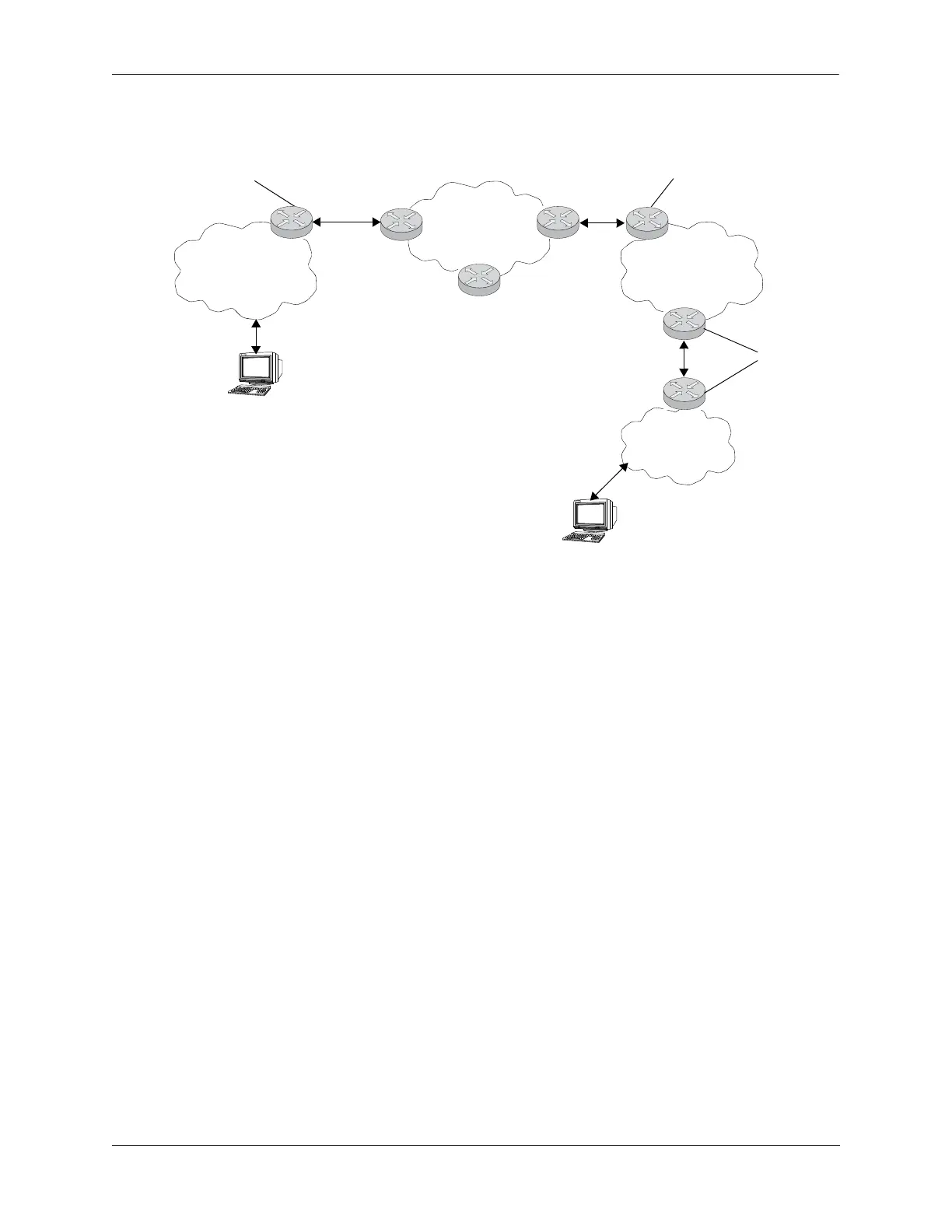
The following diagram illustrates the basic traffic flow between native IPv6 hosts and 6to4 sites:
In the above diagram:
1 The 6to4 relay router advertises a route to 2002::/16 on its IPv6 router interface.
2 The IPv6 host traffic received by the relay router that has a next hop address that matches 2002::/16 is
routed to the 6to4 tunnel interface configured on the relay router.
3 The traffic routed to the 6to4 tunnel interface is then encapsulated into IPv4 headers and sent to the
destination 6to4 router over the IPv4 domain.
4 The destination 6to4 router strips the IPv4 header and forwards it to the IPv6 destination host.
For more information about configuring an IPv6 6to4 tunnel interface, see “Configuring an IPv6
Interface” on page 17-13 and “Configuring IPv6 Tunnel Interfaces” on page 17-17. For more detailed
information and scenarios by using 6to4 tunnels, refer to RFC 3056.
Configured Tunnels
A configured tunnel is where the endpoint addresses are manually configured to create a point-to-point
tunnel. This type of tunnel is similar to the 6to4 tunnel on which IPv6 packets are encapsulated in IPv4
headers to facilitate communication over an IPv4 network. The difference between the two types of
tunnels is that configured tunnel endpoints require manual configuration, whereas 6to4 tunneling relies on
an embedded IPv4 destination address to identify tunnel endpoints. Additionally, IPv6 multicast traffic
can be sent over configured tunnels allows RIPng and OSPFv3 to run over a configured tunnel.
For more information about IPv6 configured tunnels, see “Configuring IPv6 Tunnel Interfaces” on
page 17-17. For more detailed information about configured tunnels, refer to RFC 4213.
IPv6 Domain
IPv4 Domain
6to4 Host
IPv6 Host
IPv6/IPv4 6to4
Relay Router
6to4 Site
IPv6 6to4
Border Router
IPv6 Site
IPv6
Router
 Loading...