Configuring VRRP VRRPv2 Application Example
OmniSwitch AOS Release 8 Network Configuration Guide December 2017 page 23-20
VRRPv2 Application Example
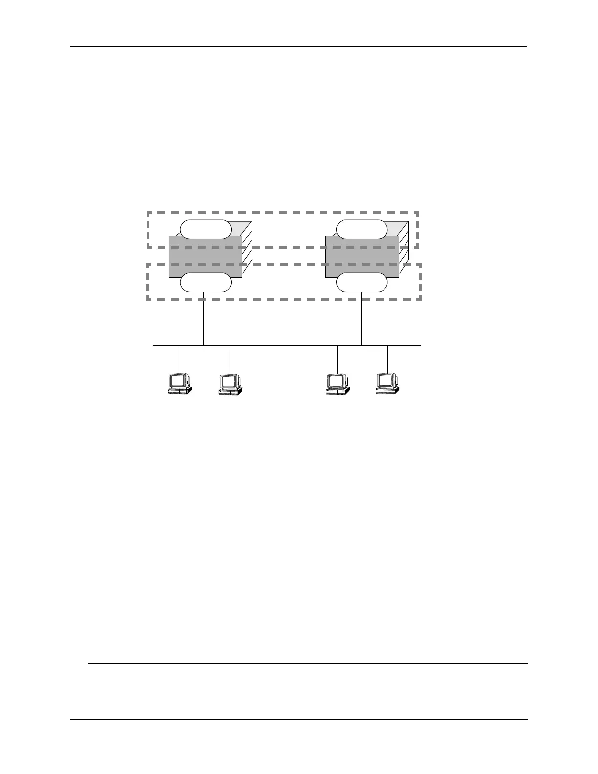
In addition to providing redundancy, VRRP can assist in load balancing outgoing traffic. The figure below
shows two virtual routers with their hosts splitting traffic between them. Half of the hosts are configured
with a default route to virtual router 1’s IP address (10.10.2.250), and the other half are configured with a
default route to virtual router 2’s IP address (10.10.2.245).
The CLI commands used to configure this setup are as follows:
1 First, create two virtual routers for VLAN 5. (Note that VLAN 5 must already be created and available
on the switch.)
-> vrrp 1 5
-> vrrp 2 5
2 Configure the IP addresses for each virtual router.
-> vrrp 1 5 ip 10.10.2.250
-> vrrp 2 5 ip 10.10.2.245
3 Enable the virtual routers.
-> vrrp 1 5 admin-state enable
-> vrrp 2 5 admin-state enable
Note. The same VRRP configuration must be set up on each switch. The VRRP router that contains, or
owns, the IP address will automatically become the master for that virtual router. If the IP address is a
virtual address, the virtual router with the highest priority will become the master router.
VRRP Router
OmniSwitch A
VRRP Router
OmniSwitch B
Virtual Routers
VRID 1
10.10.2.250
VRID 2
10.10.2.245
VRRP Redundancy and Load Balancing
Master 1
10.10.2.24510.10.2.250
default gateway 10.10.2.250
default gateway 10.10.2.245
clients 3 and 4clients 1 and 2
Backup 2
Backup 1
Master 2
VLAN 5
 Loading...