2. CNC Monitor Screen
2.7 Diagnosis
I - 173
2.7.4 PLC Interface Diagnosis of CNC CPU
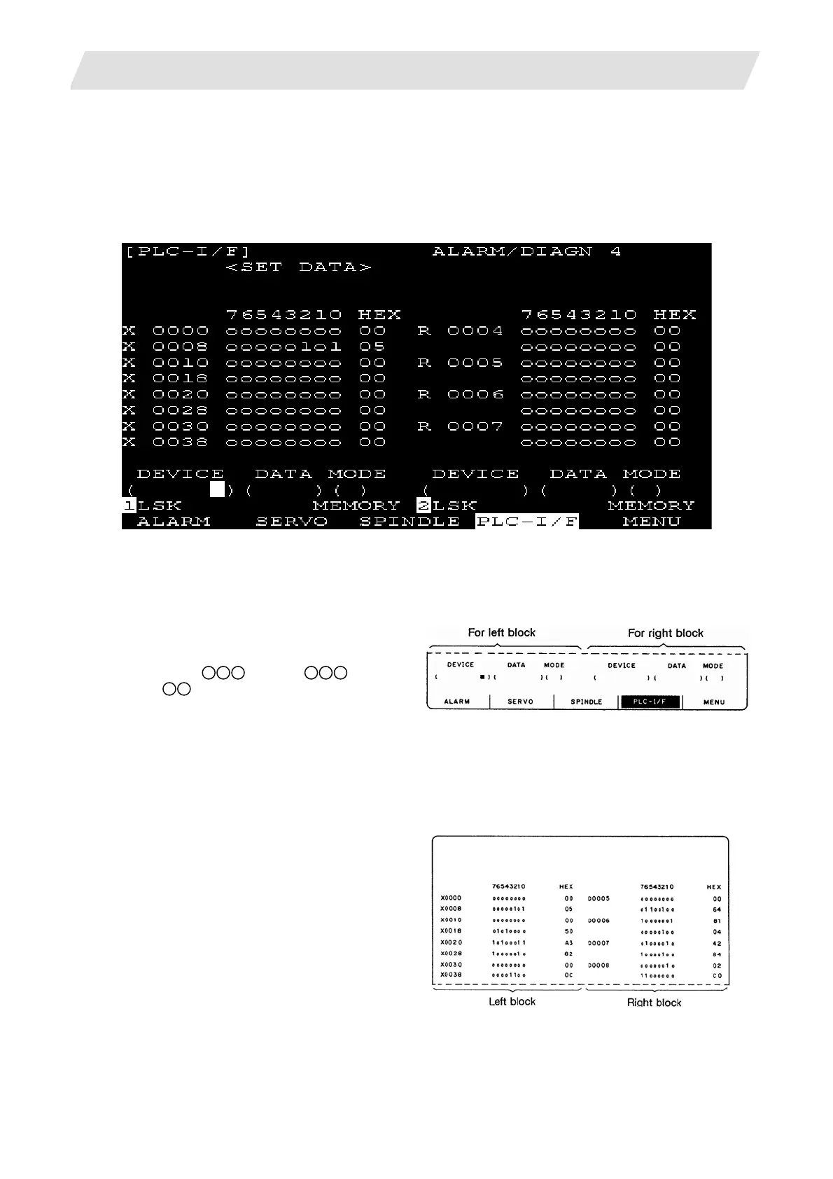
When the menu [PLC-I/F] is pressed, the CNC CPU's PLC-I/F screen is displayed.
The PLC-I/F screen enables you to set and display input/output signals for PLC (Programmable Logic
Control Unit) control.
It can be used to check machine sequence operation during PLC development, check input/output data
between control unit and PLC in operation trouble, and make forcible definition.
2.7.4.1 PLC-I/F Setting and Display
(1) Dat
a setting area
DEVICE ( )
Set the device number used with PLC
(input X
, output Y , and timer
T
).
DATA ( )
To forcibly define PLC data, set data corresponding to the setup device number. Set 1 or 0 for bit
data. Set hexadecimal (HEX) data for byte data.
MODE ( )
Specify the type of forcible definition. 1: Single-shot type
2: Modal type
(2) Device data display area
Data corresponding to the device numbers
specified in the setting area is displayed.
Data is displayed in both binary notation and
hexadecimal notation.
The device numbers can be displayed in the
left and right blocks separately.
 Loading...


