III - 7
3. Display on 7-segment LED
3.2 Notes
3.2 Notes
(1) Display priority
When several alarms occurred at the same time, the most crucial alarm is selected according to the
following chart and displayed.
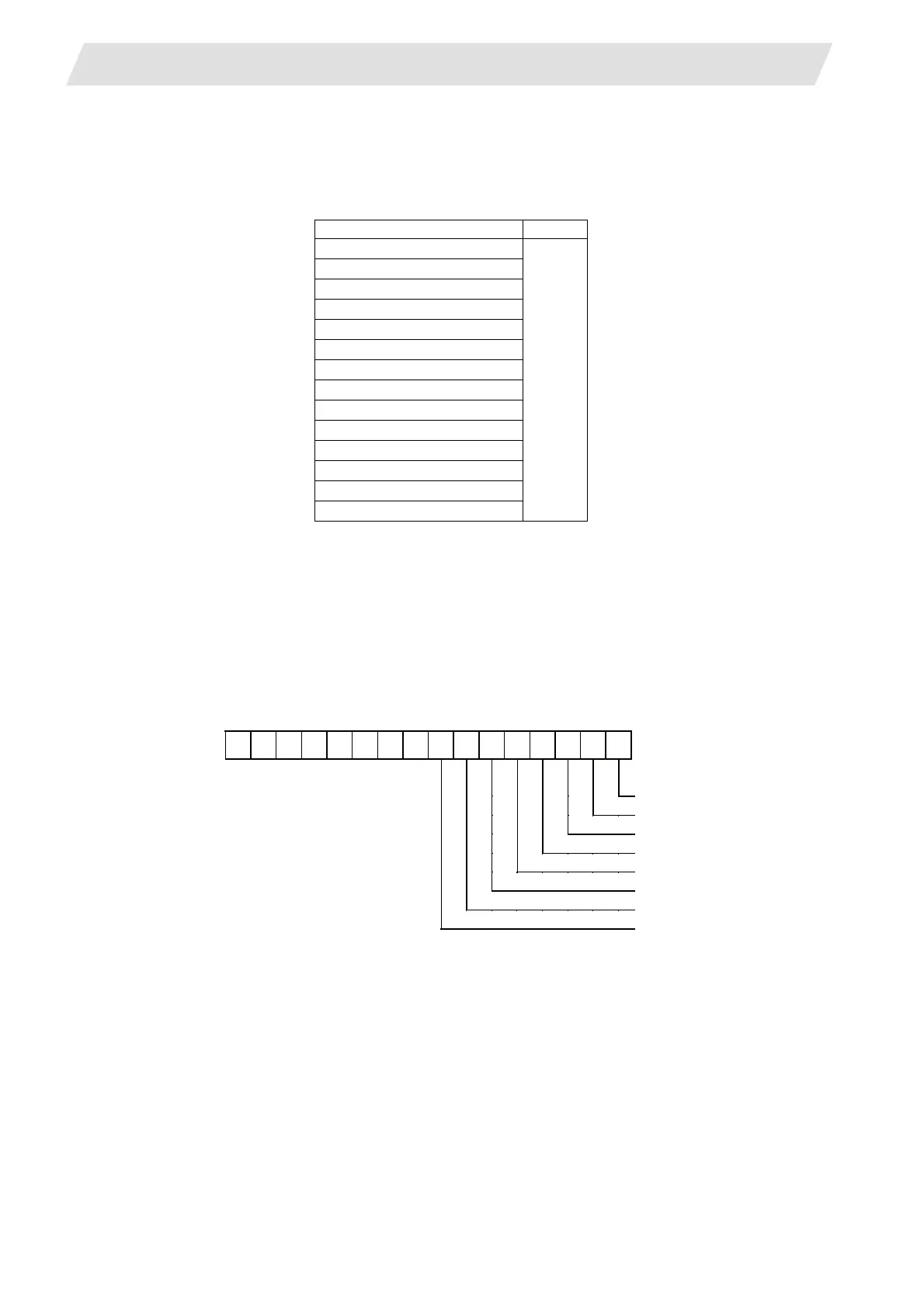
(2) Display of axes
Each axis is allocated to each bit according to the following rule. Hexadecimal number is displayed on 7-
segment LED.
(Note 1) "*" in the first digit indicates the spindle.
(Note 2) "_" in the first digit indicates PLC axis.
(Note 3) When an error occurred on several axes, one of the axes is indicated. The indication
priority is; (1) NC axis, (2) PLC axis and then (3) spindle.
(Example 1) “004” (bit2 is ON) for 3rd NC axis
(Example 2) “003” (bit0 and bit1 is ON) for 1st and 2nd NC axis
(Example 3) “*01” (bit0 is ON) for spindle(S)
(Example 4) "_28" (bit3 and bit5 are ON) for 4th PLC axis and 6th PLC axis
(Example 5) "011" (bit0 and bit1 are ON) for 1st and 5th NC axes, 2nd PLC axis and spindle(S)
Alarm type Priority
WDT error
High
↑
↓
Low
Battery alarm
Multi-CPU error
System alarm
Servo alarm
MCP alarm
Emergency stop
Built-in PLC alarm
Program error
Servo warning
MCP warning
System warning
Operation error
Stop code
bit FEDCBA9876543210
Axis name(Spindle)
1st (S)
2nd (T)
3rd (M)
4th (N)
5th (P)
6th (Q)
7th (R)
8th
 Loading...


