EasyManua.ls Logo

Mitsubishi C70 User Manual

Mitsubishi C70
536 pages
To Next Page IconTo Next Page
To Previous Page IconTo Previous Page
Page #45 background imageLoading...
Page #45 background image
2. CNC Monitor Screen
2.2 Monitor
I - 20
2.2.1.1 Position Display Counter Zero and Origin Zero
Coun
ter
Zero
The POSITION display only is set to zero and the absolute value data remains unchanged.
Origin Zero
This sets both POSITION display and absolute value data to zero.
It is equivalent to G92 X0 Y0 Z0 ;.
(Note) Origin zero is valid only when "#1123 origin" is set to 0.
In the following operations, the [INPUT] key
leads to the counter zero function and the [C.B
CAN] key leads to the origin zero (set zero)
function.
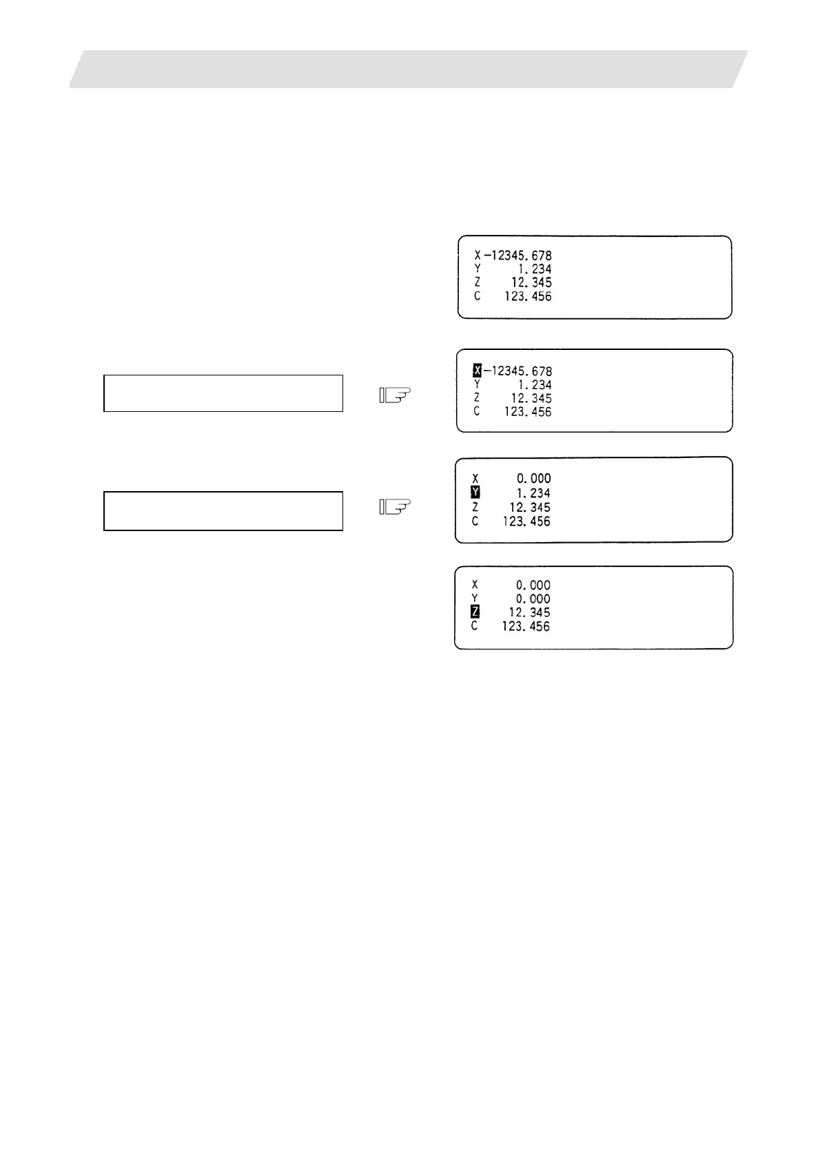
Press the address key [X]
.
1) The address indication corresponding to the
key is highlighted.
Press the [INPUT] key (counter zero)
or [C.B CAN] key (origin zero).
1) The axis position data is set to zero and the
next axis name is highlighted.
2) By repeatedly pressing the [INPUT] or [C.B
CAN] key, the position data of other axes
can be cleared to zero.
3) Upon completion of zero clear of final axis,
the display is no longer reversed.
4) If you press an axis address key midway,
the address of specified axis is highlighted.
5) When you press a key other than axis
address key, the display is no longer
reversed.

Table of Contents

Question and Answer IconNeed help?

Do you have a question about the Mitsubishi C70 and is the answer not in the manual?

Mitsubishi C70 Specifications

General IconGeneral
BrandMitsubishi
ModelC70
CategoryControl Unit
LanguageEnglish

Summary

Introduction

Details described in this manual

Outlines the content covered in this manual, including how to operate C70 screens.

Precautions for Safety

DANGER

Safety precautions for handling that could lead to imminent fatalities or major injuries.

WARNING

Safety precautions for handling that could lead to fatalities or major injuries.

CAUTION

Safety precautions for handling that could lead to injuries or physical damage.

I. SCREEN OPERATIONS

1. Setting and Display Unit

Covers the basic setup and display functionalities on the GOT unit.

2. CNC Monitor Screen

Details the information displayed and set on the machine and NC system.

II. MACHINE OPERATIONS

1. Operation State

Explains the different operational states of the NC unit and their transitions.

4. Operation Mode

Describes how to select and use different operation modes like Jog, Memory, MDI.

6. Operation Panel Switch Functions

Explains the functions of various switches on the operation panel.

III. MAINTENANCE

1. Maintenance Works

Outlines essential maintenance and inspection tasks for safe and optimal C70 operation.

5. Hardware Replacement Methods

Provides instructions for replacing hardware components like modules and batteries.

6. CNC Data Input/Output

Details how to copy, delete, and manage files and data between CNC and external devices.

7. Data Backup and Restoration

Explains procedures for backing up and restoring GOT and PLC/CNC CPU data.

IV. APPENDIXES

Appendix 1. Registering and Editing Fixed Cycle Programs

Covers procedures for registering, editing, inputting, outputting, and deleting fixed cycle programs.

Appendix 4. Data Protection

Explains data protection keys and edit locks to prevent unauthorized changes to data.

Appendix 7. Explanation of Alarms

Provides detailed explanations of alarms, stop codes, servo/spindle alarms, MCP alarms, system alarms, and program errors.

Appendix 8. User Parameters

Lists and explains various user parameters for system configuration and operation.

Related product manuals