2. CNC Monitor Screen
2.3(I) Tool Offset (L system)
(Refer to "2.3 (II). Tool Offset (M system)" for Machining center system)
I - 43
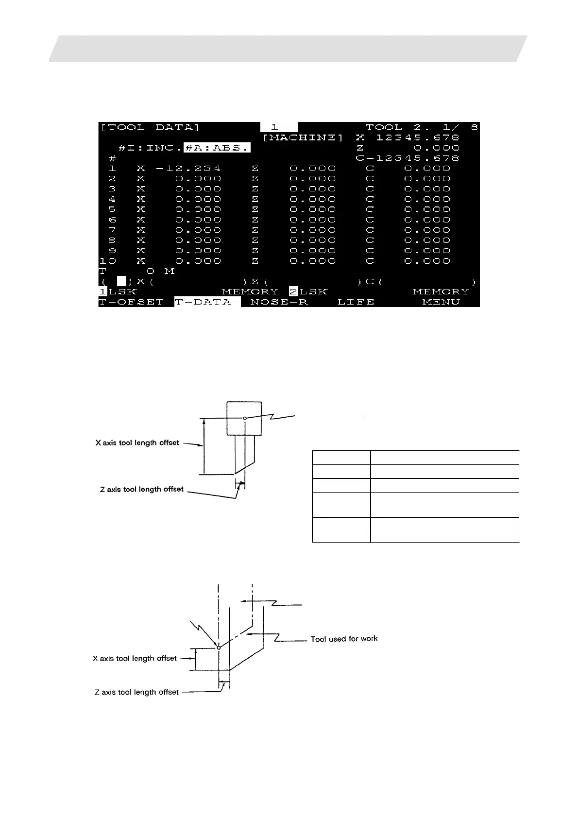
2.3.2 Tool Length Data
The TOOL DATA screen will appear when the menu [T-DATA] is pressed.
Set the tool length in respect to the programmed base position of each tool used.
When the tool compensation No. is designated by the tool command (T command), compensation is
carried out matching the wear data of the previous screen. Generally, the programmed base point position
is either the tool rest center position or the base tool nose position.
(1) Tool rest center position
Base position
Data Function
X X axis tool length compensation
Z Z axis tool length compensation
C
Additional axis tool length
compensation
MACHINE
Same value as on the
MONITOR screen.
(2) Base tool nose position
Base position
Base tool
 Loading...


