2. CNC Monitor Screen
2.3(I) Tool Offset (L system)
(Refer to "2.3 (II). Tool Offset (M system)" for Machining center system)
I - 51
2.3.2.3 Tool Presetter
(1) Outline
By using a device having a touch sensor, the tool compensation amount can be calculated just by
contacting the tool nose against the touch sensor with manual feed. The calculated results are stored
in the tool compensation amount memory.
After setting the tool compensation amount for each tool, the Z axis external workpiece coordinate
offset data can be set by cutting the edges of the workpiece with manual operation and inputting the
workpiece measurement signal.
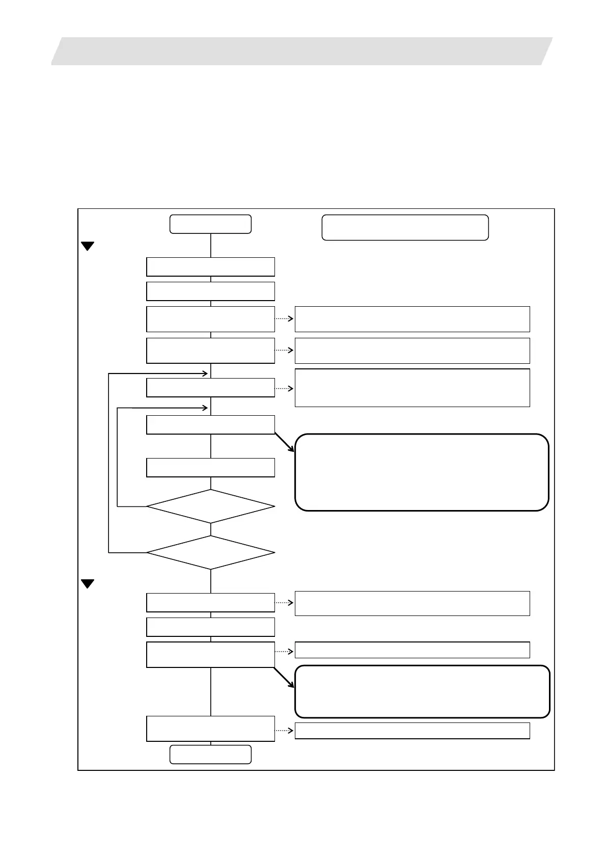
(2) Operation flow
Start of operation
Reference point return
Select manual mode
Turn tool measurement mode
TLMS
ON
Set measurement base
position
Set No. of tool to be measured
Contact tool against sensor
Select tool
Turn ON Y721 (tool measurement mode).
Preset the following axis specification parameter as the
sensor position. #2015 tlml–, #2016 tlml+
Set the compensation No. of the tool to be measured in
the R register.
Tool No.: R4720, Wear data compensation No.: R2431
♦ The axis movement will stop, and can be moved only
in the direction away from the sensor.
Set the compensation No. of the tool to be used for
cutting in the R register.
The tool length compensation amount is automatically
calculated from the contacted position, and is stored in the
tool compensation amount memory.
Tool compensation amount = Machine coordinate value
– Measurement base position (Sensor position)
The wear amount is cleared after measurement.
Retract tool
Cut workpiece edges
Measure other axes?
Measure other tools?
♦ The tool compensation amount is measured one axis at a time.
♦ Do not move the tool in the Z axis direction after cutting.
Turn tool measurement mode
[TLMS] OFF
End of operation
The Z axis workpiece coordinate offset will be measured
and set in the external workpiece offset.
Workpiece coordinate offset = Machine coordinate value
– Tool compensation data
Turn ON Y7B1 (workpiece measurement No.) Input workpiece measurement
signal
Turn OFF Y721 (tool measurement No.)
Interface and operation with NC
No
No
Yes
Yes
External workpiece offset
Tool compensation amount
 Loading...


