III - 19
5. Hardware Replacement Methods
5.1 Module Installation
5.1.2 Installation and removal of module
This section describes how to install and remove a power supply module, PLC CPU module, CNC CPU
module, I/O module, intelligent function module or another module to and from the base unit.
Installation and removal of the module from Q3□DB/Q6□B base unit
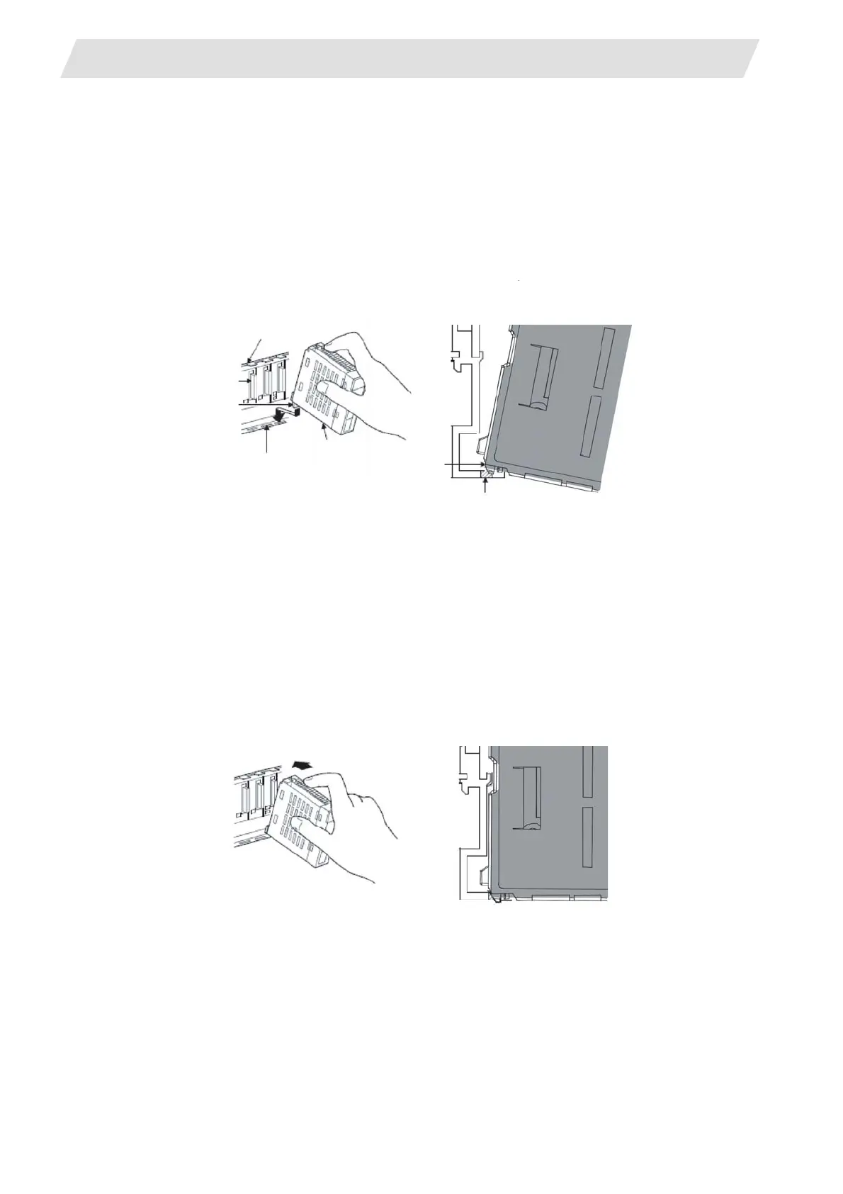
Installation
(1) Securely insert the module fixing projection into the module fixing hole so that the latch is not
misaligned.
(A) Base unit
(B) Module connector
(C) Module fixing projection
(D) Module fixing hole
(E) Module
(2) Using the module fixing hole as a fulcrum, push the module in the direction of arrow to install it
into the base unit.
(3) Make sure that the module is installed in the base unit securely.
(4) Tighten the screw of the base unit.
(Note) To avoid drop, all screws of the module must be tightened.
Module fixation screw must be prepared by the user.
Use provided module fixation screw (M3 x 13) for CNC CPU module.
(A)
(A)
(B)
(C)
(D)
(D)
(C)
(E)
(E)
 Loading...


