III - 6
3. Display on 7-segment LED
3.1 Detailed display of alarm/stop codes
(Note 1) CNC CPU LED display will not change even if a battery alarm occurs to another CPU, such as a
PLC CPU.
(Note 2) If any of the following alarms occurs independently, 7-segment LED still displays the normal state,
“run.”.
- EMG EMERGENCY STOP EXIN
- M01 OPERATION ERROR 0109 (Block start interlock)
- M01 OPERATION ERROR 0110 (Cutting block start interlock)
3.1 Detailed display of alarm/stop codes
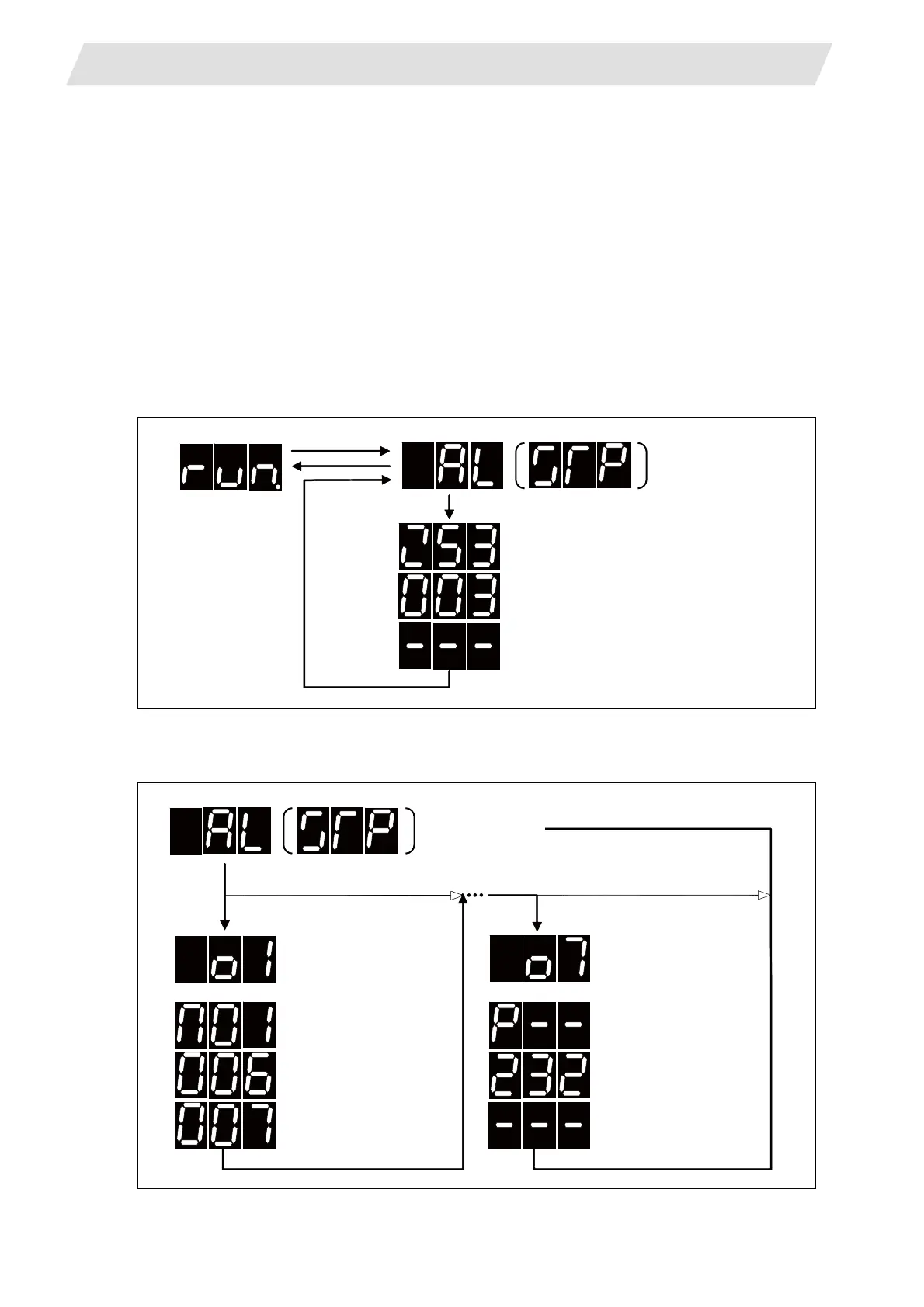
An alarm/stop code occurrence is displayed in 2 steps, report and details .
Alarm (“AL”) or stop code (“STP”) display flickers 3 times.
Details: Alarm code is displayed in 3 phases.
When multi-part system is used, the part system No. shows first, and then the alarm code appears.
Flickers 3 times
Alarm code is displayed in 3 phases
(Ex) Z53 TEMP. OVER 0003
Alarm type
Status 1
Status 2
When an alarm (stop code) occurredNormal state
0006 XYZ
When an alarm (stop code) occurred
Flickers 3 times
No alarm in the 1st part
system
Indicates the alarm display
for the 1st part system
Displays the alarm code in
3 phases
(Ex) M01 OPERATION ERROR
No alarm in the 7th part
system
Indicates the alarm display
for the 7th part system
Displays the alarm code in
3 phases
 Loading...


