2. CNC Monitor Screen
2.1 Setting and Display Unit Operation
I - 6
2.1 Setting and Display Unit Operation
2.1.1 Display Area of NC Screens
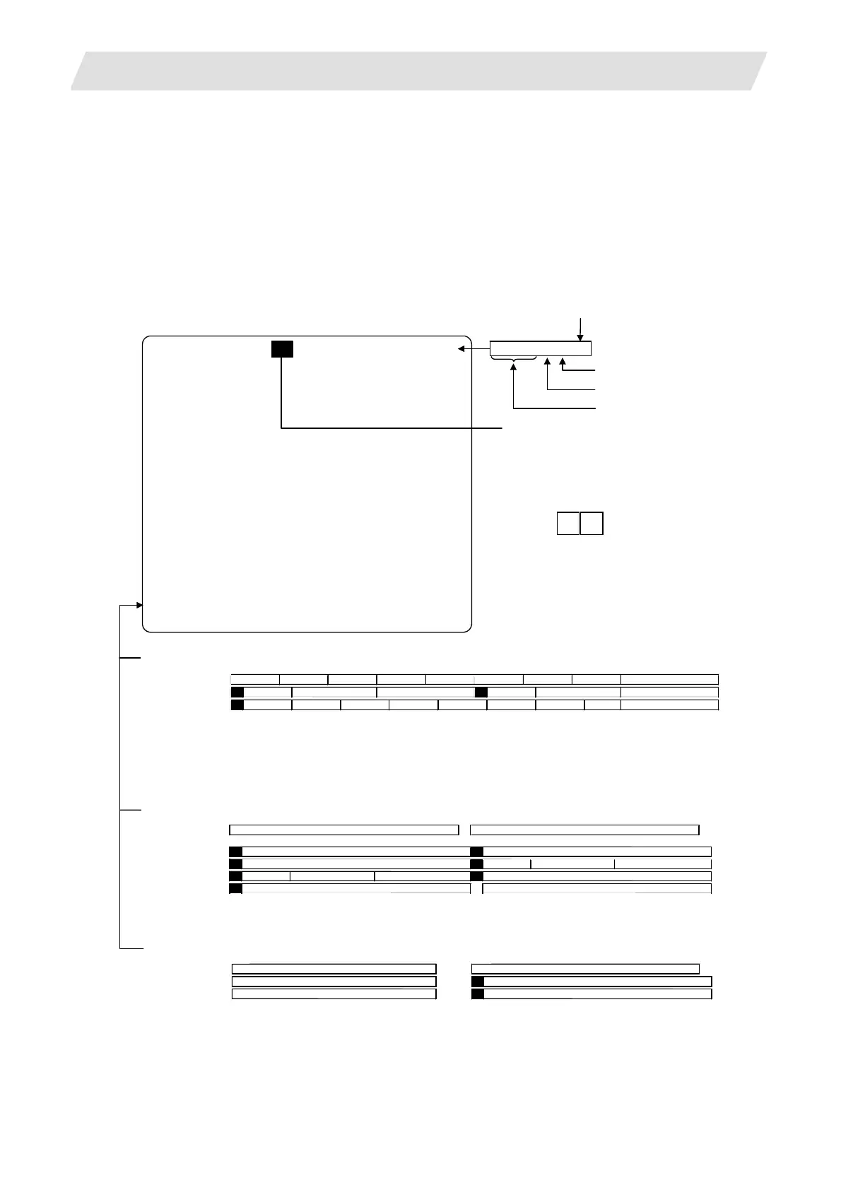
NC screen display area is divided into the following four areas:
(1) Data display area
(2) Operation status mode and alarm display area
(3) Menu display area
(4) Setting area and key operation message area
SHIFT
$
4
(
注
1)
larm during absolute position initializing (Note 2)
2
3
↑
Operation status mode display and menu display (during normal operation) (Note 1)
1-part system
2-part system 1
2
3-part system
or more
3
↑
Part system No.
$1 operation mode
Ope mode (arbitrary)ST5
ST1
(blank)
$1 operation mode
ST1
(blank)
$2 operation mode
ST6 ST7 ST8
ST1 ST2 ST3 ST4
ST5 ST6 ST7 ST8
ST1 ST2 ST3 ST4
This is displayed when 6 or more menus exist.
The selected menu is reverse-displayed.
•Alarm at $1 and $2
1 2
•Alarm at only $1
1 2
•Alarm at only $2
1 2
3
↑
Part system No.
Second alarm of arbitrary part system First alarm of arbitrary part system
First alarm of $1 Second alarm of $2
First alarm of $1 First alarm of $2
ST1 (blank) $2 operation mode
ST1
(blank) $1 operation mode
Function
name
Data display area
Key operation message area…………
……Setting area……………………………………………………
……Operation status mode/alarm display area………………
……Menu display area………………………………………………
1 MONITOR 3. 1/4
Part system name display
Maximum
number
of pages
Page number
Menu number
Function name
When using the 2-part sysytem, the part
system name will be displayed here fo
screens that can be set and displayed pe
system. The name set in parameter
“#1169 system name” will display.
The part systems can be switched over by
pressing .
…… ……
1 2 3 4 5 6 7 8 9 10 11 12 13 14 15 16 17 18 19 20 21 22 23 24 25 26 27 28 29 30 31 32 33 34 35 36 37 38 39 40
ST1: Operation status (EMG, RST, LSK, etc.)
ST2: Metric/Inch command (mm/in.)
ST3: Absolute/Incremental command mode (ABS/INC)
ST4: During tool radius compensation/Cancel (G40 to G42)
ST5: Workpiece coordinate system (G54 to G59, P01 to P48)
ST6: Executing subprogram. (SB1 to SB8)
ST7: Executing fixed cycle. (fix)
ST8: (Not used.)
larm message display (during alarm occurrence)
1-part system
2-part system
3-part system
or more
1 2 3 4 5 6 7 8 9 10 11 12 13 14 15 16 17 18 19 20 21 22 23 24 25 26 27 28 29 30 31 32 33 34 35 36 37 38 39 40
1 2 3 4 5 6 7 8 9 10 11 12 13 14 15 16 17 18 19 20 21 22 23 24 25 26 27 28 29 30 31 32 33 34 35 36 37 38 39 40
First alarm of $1
First alarm of $2
larm is highlighted and message (warning) is normally displayed.
1-part system
2-part system
3-part system
or more
larm of “ absolute position initializing“
Part system No.
First alarm of $1
First alarm of $2
First alarm of arbitrary part system
larm of “ absolute position initializing“
larm of “ absolute position initializing“
 Loading...


