Appendix 5. Table of Conversion Codes for Error Code Output
Appendix 5.1 Code Conversion Specifications
IV - 19
Appendix 5. Table of Conversion Codes for Error Code Output
With this function, the CNC alarms and errors which are normally output to CNC screen are partially
coded and output to PLC I/F device. Thus, the contents of alarms and errors can be confirmed without
CNC screen.
Appendix 5.1 Code Conversion Specifications
The following output will be made when an alarm occurs.
The message displayed in CNC screen is not converted.
(Example) When servo alarm S03 occurs
S03 SERVO WARNING 0052 XZ
xis name
larm No.
larm message
larm type
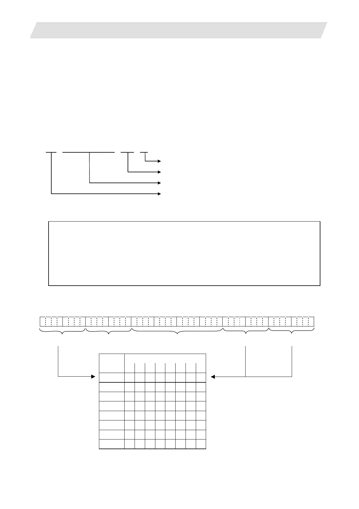
The output is as shown above on the CNC screen. However, this can be coded and output to PLC I/F
device as shown below using this function.
Alarm type
··················
Converted into a 2-digit numeral code. (Refer to the section 5.2.)
Alarm message
··········
Not coded, and not output.
Alarm No.
···················
The No. is output as HEX.
Axis name
··················
Error occurrence axis is expressed as a bit, and the bit of servo and
spindle are output separately. The head digit of the alarm without axis
name will be “0”.
The output to PLC I/F device is as follows.
0 0 0 0 0 0 0 0 0 0 1 10 0 1 1 0 0 0 0000001010010000001 0 1 0 0 0 0 0 000
bit
7 6 5 4 3 2 1 0
1st axis 0 0 0 0 0 0 0 1
2nd axis 0 0 0 0 0 0 1 0
3rd axis 0 0 0 0 0 1 0 0
4th axis 0 0 0 0 1 0 0 0
5th axis 0 0 0 1 0 0 0 0
6th axis 0 0 1 0 0 0 0 0
7th axis 0 1 0 0 0 0 0 0
8th axis 1 0 0 0 0 0 0 0
larm t
pe
Servo axis name
larm No.
Spindle name
PLC axis name
s for the servo axis name and spindle
name, the bit corresponding to the No. of
axis in which the alarm occurs is turned
on.
The max servo axis Nos. in the 1st part
system are 16, and the max spindle Nos.
in the 1st part system are 7. The spindle
alarm is output to the 1st part system.
The PLC axis name is output to the 1st
part system.
G10358/R158
(Higher side)
G10358/R158
(Lower side)
G10357/R157
(Higher side)
G10357/R157
(Lower side)
G10356/R156
(Higher side)
G10356/R156
(Lower side)
Axis name is added for the messages such as some of M01, S01 to S52, and Z70 to Z73.
The following 48 bits are used as the output PLC I/F devices.
 Loading...


