EasyManua.ls Logo

Mitsubishi C70 User Manual

Mitsubishi C70
536 pages
To Next Page IconTo Next Page
To Previous Page IconTo Previous Page
Page #60 background imageLoading...
Page #60 background image
2. CNC Monitor Screen
2.2 Monitor
I - 35
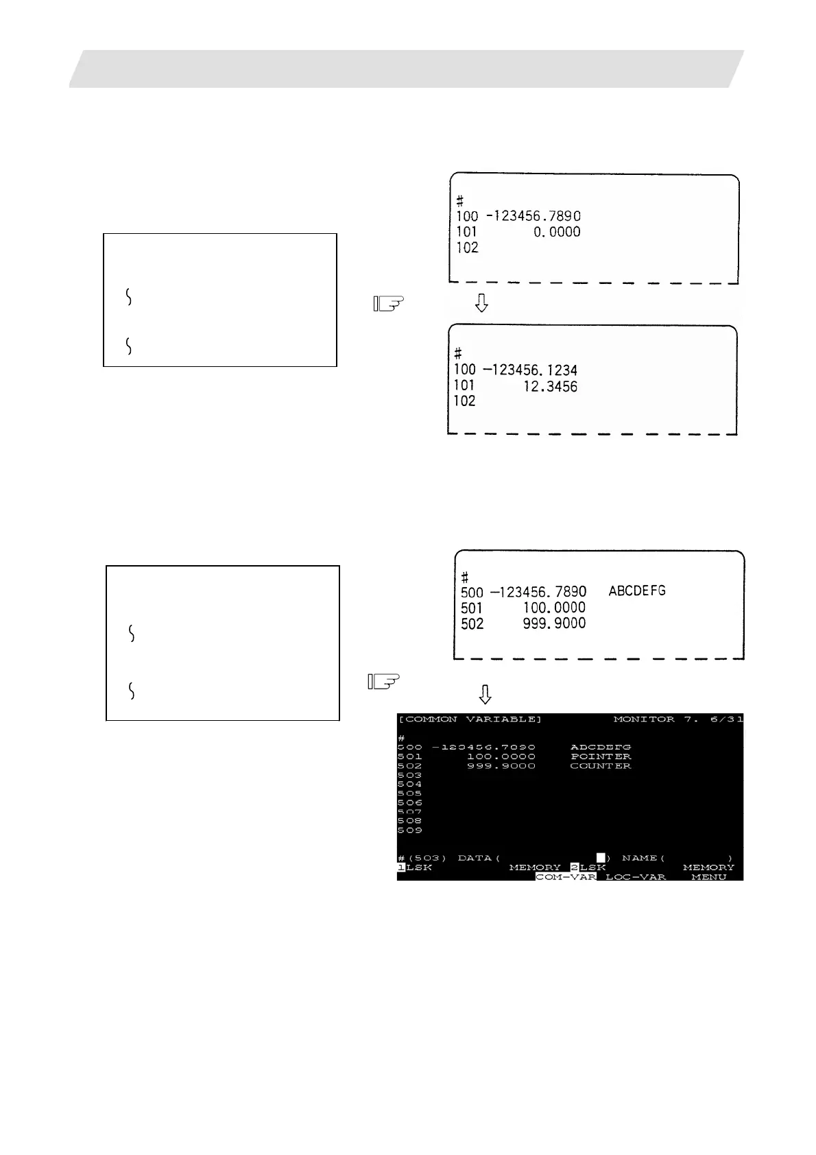
2.2.5.1 Common Variable Display
(1)
When a common variable command exists, if the block is executed, the execution result is displayed.
(Example)
The following machining program is
executed.
#101=12.3456
(2) When a command to set variable names for common variables #500~#519 by user macro exists, if the
block is executed, the setup variable name is displayed.
Variable name setting and reference commands require the user macro specifications and are limited
to 20 common variables #500~#519. The variable name is a string of up to seven alphanumeric
characters beginning with an alphabetic character. For common variables #500~#519, the variable
numbers, data, and variable names are displayed as shown below:
(Example)
The following machining program is
executed.
SETVN 501 [POINTER,
COUNTER];

Table of Contents

Question and Answer IconNeed help?

Do you have a question about the Mitsubishi C70 and is the answer not in the manual?

Mitsubishi C70 Specifications

General IconGeneral
BrandMitsubishi
ModelC70
CategoryControl Unit
LanguageEnglish

Summary

Introduction

Details described in this manual

Outlines the content covered in this manual, including how to operate C70 screens.

Precautions for Safety

DANGER

Safety precautions for handling that could lead to imminent fatalities or major injuries.

WARNING

Safety precautions for handling that could lead to fatalities or major injuries.

CAUTION

Safety precautions for handling that could lead to injuries or physical damage.

I. SCREEN OPERATIONS

1. Setting and Display Unit

Covers the basic setup and display functionalities on the GOT unit.

2. CNC Monitor Screen

Details the information displayed and set on the machine and NC system.

II. MACHINE OPERATIONS

1. Operation State

Explains the different operational states of the NC unit and their transitions.

4. Operation Mode

Describes how to select and use different operation modes like Jog, Memory, MDI.

6. Operation Panel Switch Functions

Explains the functions of various switches on the operation panel.

III. MAINTENANCE

1. Maintenance Works

Outlines essential maintenance and inspection tasks for safe and optimal C70 operation.

5. Hardware Replacement Methods

Provides instructions for replacing hardware components like modules and batteries.

6. CNC Data Input/Output

Details how to copy, delete, and manage files and data between CNC and external devices.

7. Data Backup and Restoration

Explains procedures for backing up and restoring GOT and PLC/CNC CPU data.

IV. APPENDIXES

Appendix 1. Registering and Editing Fixed Cycle Programs

Covers procedures for registering, editing, inputting, outputting, and deleting fixed cycle programs.

Appendix 4. Data Protection

Explains data protection keys and edit locks to prevent unauthorized changes to data.

Appendix 7. Explanation of Alarms

Provides detailed explanations of alarms, stop codes, servo/spindle alarms, MCP alarms, system alarms, and program errors.

Appendix 8. User Parameters

Lists and explains various user parameters for system configuration and operation.

Related product manuals