EasyManua.ls Logo

Mitsubishi C70 User Manual

Mitsubishi C70
536 pages
To Next Page IconTo Next Page
To Previous Page IconTo Previous Page
Page #63 background imageLoading...
Page #63 background image
2. CNC Monitor Screen
2.2 Monitor
I - 38
2.2.6.1 Local Variable Data Display
(1)
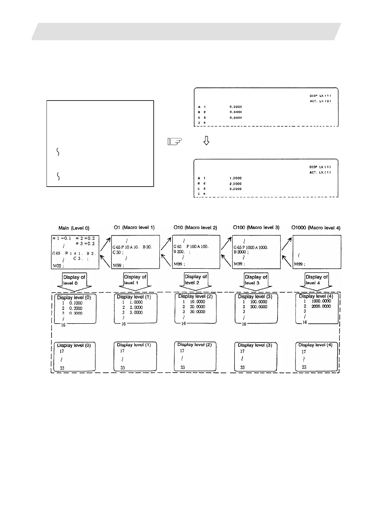
When local variable #1 - #32 command exists in user macro or argument specification is made in user
macro subprogram call, if the block is executed, the execution result is displayed.
(Example)
When the following machining
program is executed and user macro
subprogram is called, data as shown
in the right is displayed on the page
of local variable display level (1):
G65 P1 A1. B2. C3. ;
(2) The relationship between the user macro subprogram call execution and display levels is as shown
below:
(3) A local variable display page is selected by using the page keys [BACK],[NEXT] Display can be
changed as desired independently of the executing level.
(Note) The local variables are not cleared even when power is turned off. They are cleared when a macro
is called.

Table of Contents

Question and Answer IconNeed help?

Do you have a question about the Mitsubishi C70 and is the answer not in the manual?

Mitsubishi C70 Specifications

General IconGeneral
BrandMitsubishi
ModelC70
CategoryControl Unit
LanguageEnglish

Summary

Introduction

Details described in this manual

Outlines the content covered in this manual, including how to operate C70 screens.

Precautions for Safety

DANGER

Safety precautions for handling that could lead to imminent fatalities or major injuries.

WARNING

Safety precautions for handling that could lead to fatalities or major injuries.

CAUTION

Safety precautions for handling that could lead to injuries or physical damage.

I. SCREEN OPERATIONS

1. Setting and Display Unit

Covers the basic setup and display functionalities on the GOT unit.

2. CNC Monitor Screen

Details the information displayed and set on the machine and NC system.

II. MACHINE OPERATIONS

1. Operation State

Explains the different operational states of the NC unit and their transitions.

4. Operation Mode

Describes how to select and use different operation modes like Jog, Memory, MDI.

6. Operation Panel Switch Functions

Explains the functions of various switches on the operation panel.

III. MAINTENANCE

1. Maintenance Works

Outlines essential maintenance and inspection tasks for safe and optimal C70 operation.

5. Hardware Replacement Methods

Provides instructions for replacing hardware components like modules and batteries.

6. CNC Data Input/Output

Details how to copy, delete, and manage files and data between CNC and external devices.

7. Data Backup and Restoration

Explains procedures for backing up and restoring GOT and PLC/CNC CPU data.

IV. APPENDIXES

Appendix 1. Registering and Editing Fixed Cycle Programs

Covers procedures for registering, editing, inputting, outputting, and deleting fixed cycle programs.

Appendix 4. Data Protection

Explains data protection keys and edit locks to prevent unauthorized changes to data.

Appendix 7. Explanation of Alarms

Provides detailed explanations of alarms, stop codes, servo/spindle alarms, MCP alarms, system alarms, and program errors.

Appendix 8. User Parameters

Lists and explains various user parameters for system configuration and operation.

Related product manuals