Home
Mitsubishi
Control Unit
C70
Mitsubishi C70 User Manual
5
of 1
of 1 rating
536 pages
Give review
Manual
Specs
To Next Page
To Next Page
To Previous Page
To Previous Page
Loading...
III - 69
7. Data Backup
and Restoration
7.2 PLC/CNC CPU Data Ba
ckup and Restoration
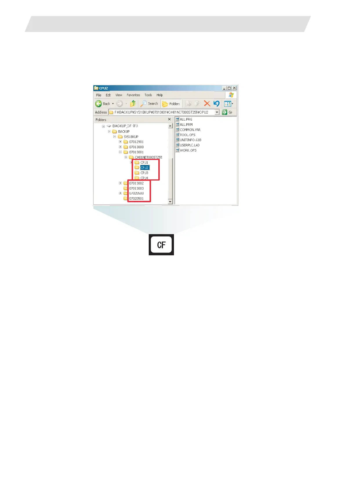
7.2.1.2 Backup Files Structure
Each backup makes a folder in a
CF card, and data is saved.
Each folder name contain
s the backup date and order No.
And, sub folders are made
for each CPU module.
337
339
Table of Contents
Default Chapter
16
Table of Contents
16
Screen Operations
24
Setting and Display Unit
26
Graphic Operation Terminal (GOT)
26
Screen Operation of GOT
27
CNC Monitor Screen
29
Setting and Display Unit Operation
31
Display Area of NC Screens
31
Screen Transition Diagram (L System)
33
Screen Transition Diagram (M System)
34
Screen Selection Procedure
35
Data Setting Method
39
Monitor
43
Position
44
Position Display Counter Zero and Origin Zero
45
Manual Numerical Value Command (S, T, M)
46
Displaying Automatic Operation Program
49
Coordinate
50
Command
52
Execution Program Monitor
52
Execution Modal Monitor
53
Total Integrating Time Display
55
Program Search
57
Memory Search
58
Common Variable
59
Common Variable Display
60
Common Variable Data Deleting
61
Common Variable Setting
61
Local Variable
62
Local Variable Data Display
63
I) Tool Offset (L System)
64
Wear Data
65
Erasing the Tool Offset Data
66
Setting Tool Offset Data
66
Tool Wear and Tool Length Data Setting Mode (Incremental/Absolute)
67
Tool Length Data
68
Manual Tool Length Measurement I
69
Manual Numerical Command Operation on the TOOL DATA Screen (M, T)
75
Tool Presetter
76
Tool Nose Data
81
Tool Life Management I ("#1096 T_L Type" Is 1)
82
Conditions for Counting (Incrementing)
83
Tool Life Management Method
83
Cautions
84
Erasing Tool Life Management Data in Display Screen Units
84
Setting Tool Life Management Data
84
Tool Life Management II ("#1096 T_Ltype" Is 2)
85
Group Registration
86
Tool Life Incrementation Methods
89
Parameters
90
Outline of Functions
91
Tool Registration
91
Tool Registration in the Magazine Pot
92
Deleting Tool Registration Data
93
Tool Registration in the Spindle, Standby and Indexing Areas
93
Manual Numerical Command Operation (M, T) on the TOOL REGISTRATION Screen
94
Workpiece Coordinate
94
II) Tool Offset (M System)
95
Tool Offset
96
Tool Offset Data Clear
97
Tool Offset Data Setting
97
Tool Offset Data Setting Modes (Absolute and Incremental)
97
Manual Tool Length Measurement
100
Manual Numeric Command Operation on the TOOL OFFSET Screen (M, T)
103
Function Outline
104
Tool Registration
104
Tool Registration in Magazine Pot
105
Tool Registration Data Clear
106
Tool Registration in HEAD, NEXT, and INDEX
106
Manual Numeric Command Operation on the TOOL REGISTRATION Screen (M, T)
107
Function Outline
108
Tool Life
108
TOOL LIFE Screen Data Display
109
TOOL LIFE Data Display and Setting (TOOL LIFE Data Screen
113
Clear of All TOOL LIFE Data (HEAD, NEXT, GROUP LIST Screen
114
Workpiece Coordinate
115
Displaying Machine Position Data
116
Setting External Workpiece Coordinate System Offset Data
116
Setting Workpiece Coordinate System Offset Data
116
Parameters
117
Control Parameters
119
Machining Parameters
119
Process Parameters
119
Axis Parameters
120
Barrier Data
120
Setup Parameters
121
Program
122
Function Outline
123
Edit Type
124
Menu Function
125
MDI Screen Menu Function
126
EDIT Screen Menu Function
129
Common Operation between Screen Editing and Word Editing
133
Program Edit Operation
133
Screen Editing
136
Word Editing
142
MDI Data Registration in Memory
163
MDI Screen Extension Operation
163
Edit Data Call
164
Edit Screen Extension Operation
164
New Program Registration and Preparation
168
Data In/Out
169
Program Erase
170
Program File
173
Machining Program Copy
175
Program Copy
175
Machining Program Condense
176
Machining Program Merge
177
Changing the Machining Program Number
178
Diagnosis
179
Alarm Message
180
Tracing of Alarm and Stop Codes
181
Servo Monitor
182
Servo Diagnosis
185
Power Supply Diagnosis
186
Synchronous Error
188
Spindle Monitor
189
Spindle Diagnosis
197
PLC Interface Diagnosis of CNC CPU
198
PLC-I/F Setting and Display
198
PLC Device Data Display
201
PLC Interface Signal Forcible Definition (Single-Shot Type)
202
PLC Interface Signal Forcible Definition (Modal Type)
203
Diagnosis Executed When an Emergency Stop Status Occurs
204
ABS Servo Monitor
205
Absolute Position Monitor
205
Absolute Position Initialization
206
PLC Axis Monitor
208
Operation History
209
Diagnosis of Operation History and the Occurrence Time of History (History Data)
210
Correspondence of Operation Keys and Key History
211
Input/Output Signal History Covering Range
213
Suspending the Operation History Function
213
Saving the Operation History Data
214
Switching the History Display
214
Clearing the Operation History and the Occurrence Time of History (History Data)
215
Outputting the Storage Data for Operation History
215
Setting and Displaying the Time and Date of Occurrence of Operation History Data
215
Precautions
217
S/W Module Tree (NC System)
218
S/W Module Tree(2) (Drive Unit)
218
System Configuration
218
H/W Monitor
219
NC Data Sampling
220
Display Items
221
Parameters
222
Address Designation
228
Data Output Format
230
Outputting the Data
231
Flow of the Operation
232
Machine Operations
234
Operation State
237
Operation State Transition Diagram
237
Power off
238
Not Ready
238
Ready
239
Automatic Operation Pause
239
Automatic Operation Start
239
Automatic Operation Stop
239
Reset
239
Indicator Lamps
240
NC Unit Ready
240
Automatic Operation Busy
240
Automatic Operation Start Busy
240
Automatic Operation Pause Busy
240
Return to Reference Point
240
NC Alarm
240
M00
240
M02/M30
240
Reset Switch and Emergency Stop Button
241
Reset Switch
241
Emergency Stop Button
241
Operation Mode
242
Mode Selection Switch
242
Jog Feed Mode
243
Rapid Traverse Feed Mode
244
Return to Reference Position Mode
245
Incremental Feed Mode
247
Handle Feed Mode
248
Memory Mode
249
MDI Operation Mode
250
Operation Panel Switches in Operation Mode
251
Rapid Traverse Override
251
Cutting Feed Override
251
Manual Feedrate
251
Handle/Incremental Feed Magnification Factor
252
Handle Feed Axis Selection
252
Manual Pulse Generator
252
Cycle Start and Feed Hold
253
Feed Axis Selection
253
Operation Panel Switch Functions
254
All Axes Machine Lock
254
Chamfering (L System)
254
Miscellaneous Function Lock
254
Single Block
254
Dry Run
255
Manual Override
255
Override Cancel
255
Optional Stop
255
Optional Block Skip
256
Manual Absolute
257
Error Detect
258
Follow-Up Function
258
Axis Removal
258
Manual/Automatic Synchronous Feed
258
Handle Interruption
259
Interruptible Conditions
259
Outline
259
Axis Movement Speed Resulting from Interruption
260
Interruption Effective Axis
260
Path Resulting after Handle Interruption
261
Handle Interruption in Tool Radius Compensation
263
Interrupt Amount Reset
265
Operation Sequence
266
Maintenance
268
Maintenance Works
271
Instruction of Inspection Works
271
Daily Inspection
273
Display on 7-Segment LED
274
Detailed Display of Alarm/Stop Codes
275
Notes
276
Examples of LED Display
279
Periodic Inspection
286
Hardware Replacement Methods
287
Module Installation
287
Instructions for Handling
287
Installation and Removal of Module
288
Battery for CNC CPU
290
Battery Life for CNC CPU
290
CNC CPU Battery Replacement Procedure
291
Battery Inside PLC CPU
292
Battery Life
292
Replacement Procedure for Battery Inside PLC CPU
293
CNC Data Input/Output
294
Screen Transition to the "CNC Data In/Out" Screen
294
Setting Communication
295
CNC Data In/Out" Screen Display
298
Operation Windows
301
Device Selection Window
301
Function Selection Window
301
CNC Data Selection Window
302
Copy Confirmation Window
303
Overwrite Confirmation Window
304
Delete Confirmation Window
305
Key Window
306
Selecting the Function
308
Selecting the Device
309
Selecting the Directory
310
Selecting the Directory and a File
311
Copying a File
312
Copying any File Other than the SRAM.BIN File
312
Deleting Files
314
Refreshing the List
317
Stop the USB Drive
318
Creating a Directory
319
Changing a File Name When Outputting the File
320
Summary of Screen Transition from the "CNC Data In/Out" Screen
322
Various Status
323
Data Protection
323
CNC Data
324
Messages
326
Parameters
330
Signals
330
Restrictions
330
Data Backup and Restoration
331
GOT Data Backup and Reinstallation
331
Backup Procedures
331
Reinstallation Procedures
333
PLC/CNC CPU Data Backup and Restoration
334
Backup Procedures
335
Data Backup
335
Backup Files Structure
338
Data Restoration
339
Restoration Procedures
340
Appendixes
344
Appendix 1. Registering and Editing Fixed Cycle Programs
346
Appendix 1.1 Parameter for Fixed Cycle Operation
346
Appendix 1.2 Inputting a Fixed Cycle Program
346
Appendix 1.3 Outputting a Fixed Cycle Program
346
Appendix 1.4 Deleting a Fixed Cycle Program
346
Appendix 1.5 Standard Fixed Cycle Subprogram
347
Appendix 2. List of Function Codes
359
Appendix 3. List of Command Value Ranges
360
Appendix 4. Data Protection
361
Appendix 4.1 Data Protection Key
361
Appendix 4.2 Edit Lock B, C
363
Appendix 5. Table of Conversion Codes for Error Code Output
364
Appendix 5.1 Code Conversion Specifications
364
Appendix 5.2 Code Table
365
Appendix 5.3 Restrictions
367
Appendix 6. Operation Messages on Setting Display Unit
368
Appendix 6.1 Operation Errors
368
Appendix 6.2 Operator Messages
375
Appendix 6.3 Dialog Error Messages on Input/Output Screen
379
Appendix 7 Explanation of Alarms
381
Appendix 7.1 Operation Errors (M)
381
Appendix 7.2 Stop Codes (T)
398
Appendix 7.3 Servo/Spindle Alarms (S)
405
Appendix 7.3.1 Servo Errors (S01/S03/S04)
405
Appendix 7.3.2 Initial Parameter Errors (S02)
420
Appendix 7.3.3 Parameter Errors (S51)
422
Appendix 7.3.4 Servo Warnings (S52)
423
Appendix 7.4 MCP Alarms (Y)
426
Appendix 7.5 System Alarms (Z)
444
Appendix 7.6 Absolute Position Detection System Alarms (Z7*)
453
Appendix 7.7 Emergency Stop Alarms (EMG)
457
Appendix 7.8 Auxiliary Axis Operation Errors (M)
461
Appendix 7.9 Built-In PLC Alarms (U)
463
Appendix 7.10 Multi CPU Errors (A)
464
Appendix 7.11 Network Errors (L)
495
Appendix 7.12 Program Errors (P)
505
Appendix 8 User Parameters
525
Revision History
532
5
Based on 1 rating
Ask a question
Give review
Questions and Answers:
Need help?
Do you have a question about the Mitsubishi C70 and is the answer not in the manual?
Ask a question
Mitsubishi C70 Specifications
General
Brand
Mitsubishi
Model
C70
Category
Control Unit
Language
English
Related product manuals
Mitsubishi Wi-Fi Control
12 pages
Mitsubishi MELDAS MDS-C1
330 pages
Mitsubishi FX2N
70 pages
Mitsubishi AD75M2
746 pages
Mitsubishi Q Series
244 pages
Mitsubishi A1SD75M3
746 pages
Mitsubishi A1SD75M2
746 pages
Mitsubishi M80 series
648 pages
Mitsubishi QJ72LP25-25
20 pages
Mitsubishi M800S series
648 pages
Mitsubishi MELSEC-F FX-1GM
143 pages
Mitsubishi Melsec-A AJ65SBT
112 pages
 Loading...


