2. CNC Monitor Screen
2.7 Diagnosis
I - 176
2.7.4.2 PLC Device Data Display
Monitor di
splay of state signals and register data used with PLC can be made.
When the PLC-I/F screen is first selected, 8-byte input/output data starting at device X0000 is displayed in
the left block; 8-byte input/output data starting at device Y0000 is displayed in the right block.
The screen always monitor-displays the PLC signal state. When PLC signal changes, the displayed state
also changes with the PLC signal change.
However, a lag occurs between PLC signal change and signal display, thus signal display may be delayed
or a response to a very short signal change may not be made.
(1) Display device number setting
Set the device number in DEVICE ( ). If a different device number or device address is set in the
right DEVICE ( ), the specified device numbers are displayed in the left and right halves of the
screen from the display area top to bottom.
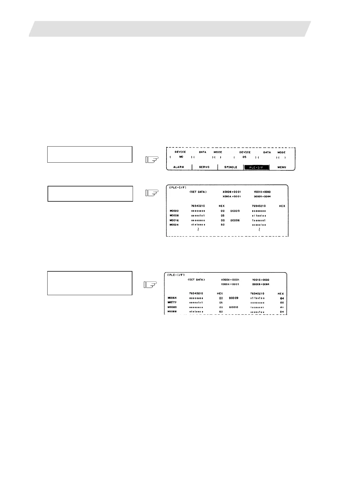
(Example 1)
Set M0 in left DEVICE ( ) and
D5 in right DEVICE ( ).
Press the [INPUT] key.
(2) Device number display change in 8-byte units
The current device number display at the top can be changed in 8-byte units by using the [BACK] or
[NEXT] key.
When the display screen shown
in Example 1 appears, press
the [NEXT] key once.
(3) When the last device number is exceeded by feeding pages, the data display screen of the last device
number remains.
(4) If a number exceeding the preset numbers in specifications or an invalid address is set, a setting error
results.
 Loading...


