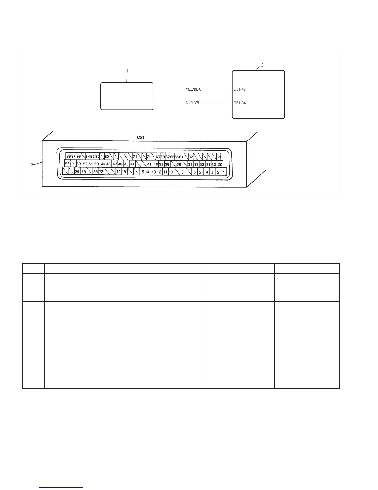
1. A / C control module
2. ECM
6-58 ENGINE DIAGNOSIS (RHZ ENGINE WITH SINGLE-CONNECTOR ECM)
DTC P1110 A/C SIGNAL CIRCUIT MALFUNCTION
WIRING DIAGRAM
DTC CONFIRMATION PROCEDURE
1) Connect scan tool to DLC with ignition switch OFF.
2) Turn ON ignition switch and clear DTC, pending DTC and freeze flame data by using scan tool.
3) Start engine and turn on A/C switch and heater blower fan switch.
4) Check DTC and pending DTC by using scan tool.
TROUBLESHOOTING
STEP ACTION YES NO
1 Was “ENGINE DIAG. FLOW TABLE” performed? Go to Step 2. Go to “ENGINE
DIAG. FLOW
TABLE”.
2 Check Wire Harness
1) Remove ECM cover from ECM referring to
“Voltage Check” in this section.
2) Check voltage between C51-84 and ground at
engine idling.
Are they as follows?
D A/C switch and heater blower switch OFF: 0 V
D A/C switch and heater blower switch ON: about 12 V
Poor C51-84
connection.
If OK, substitute a
known-good ECM and
recheck.
D “YEL/BLK” wire
open or short or
D Poor A/C control
module connector
connection
If all are in good
condition, substitute
a known-good A/C
control module and
recheck.

 Loading...


