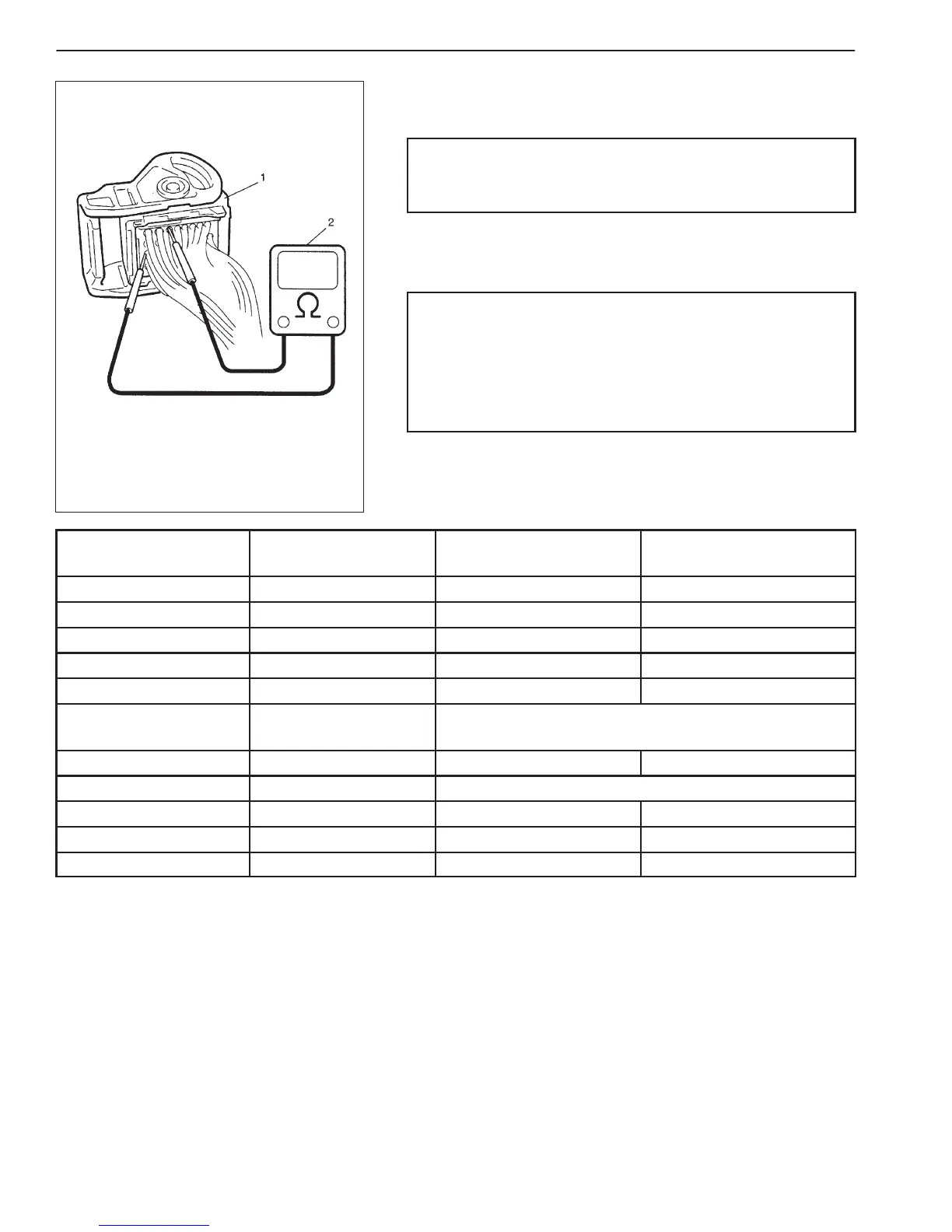
1. ECM / PCM coupler disconnected
2. Ohmmeter
6-1-6 ENGINE DIAGNOSIS (RHZ ENGINE WITH TRIPLE-CONNECTOR ECM)
Resistance Check
1) Disconnect couplers from ECM/PCM with ignition switch OFF.
CAUTION:
Do not touch terminals of ECM/PCM itself or connect
voltmeter or ohmmeter.
2) Check resistance between each pair of terminals of discon-
nected couplers as listed in the following table.
CAUTION:
D Be sure to connect ohmmeter probe from wire harness
side of coupler.
D Be sure to turn OFF ignition switch for this check.
D Resistance in table represents that when parts temper-
ature is 20_C (68_F).
TERMINAL CIRCUIT
STANDARD
RESISTANCE
CONDITION
E229-2 to E229-9 Fuel injector No.1 Max. 0.6 Ω —
E229-25 to E229-17 Fuel injector No.2 Max. 0.6 Ω —
E229-26 to E229-18 Fuel injector No.3 Max. 0.6 Ω —
E229-1 to E229-10 Fuel injector No.4 Max. 0.6 Ω —
E228-4 to E228-3 CKP sensor 315 – 405 Ω At 20_C (68_F)
E228-21 to E228-20 Fuel temp. sensor
Refer to “FUEL TEMPERATURE SENSOR” in Section
6E3.
E228-1 to E228-14 Fuel pressure regulator 2 – 3 Ω At 20_C (68_F)
E228-8 to E228-9 ECT sensor Refer to “ECT SENSOR” in Section 6E3.
E228-37 to Body ground Ground Below 1.5 Ω —
E228-38 to Body ground Ground Below 1.5 Ω —
E227-32 to Body ground Ground Below 1.5 Ω —

 Loading...


