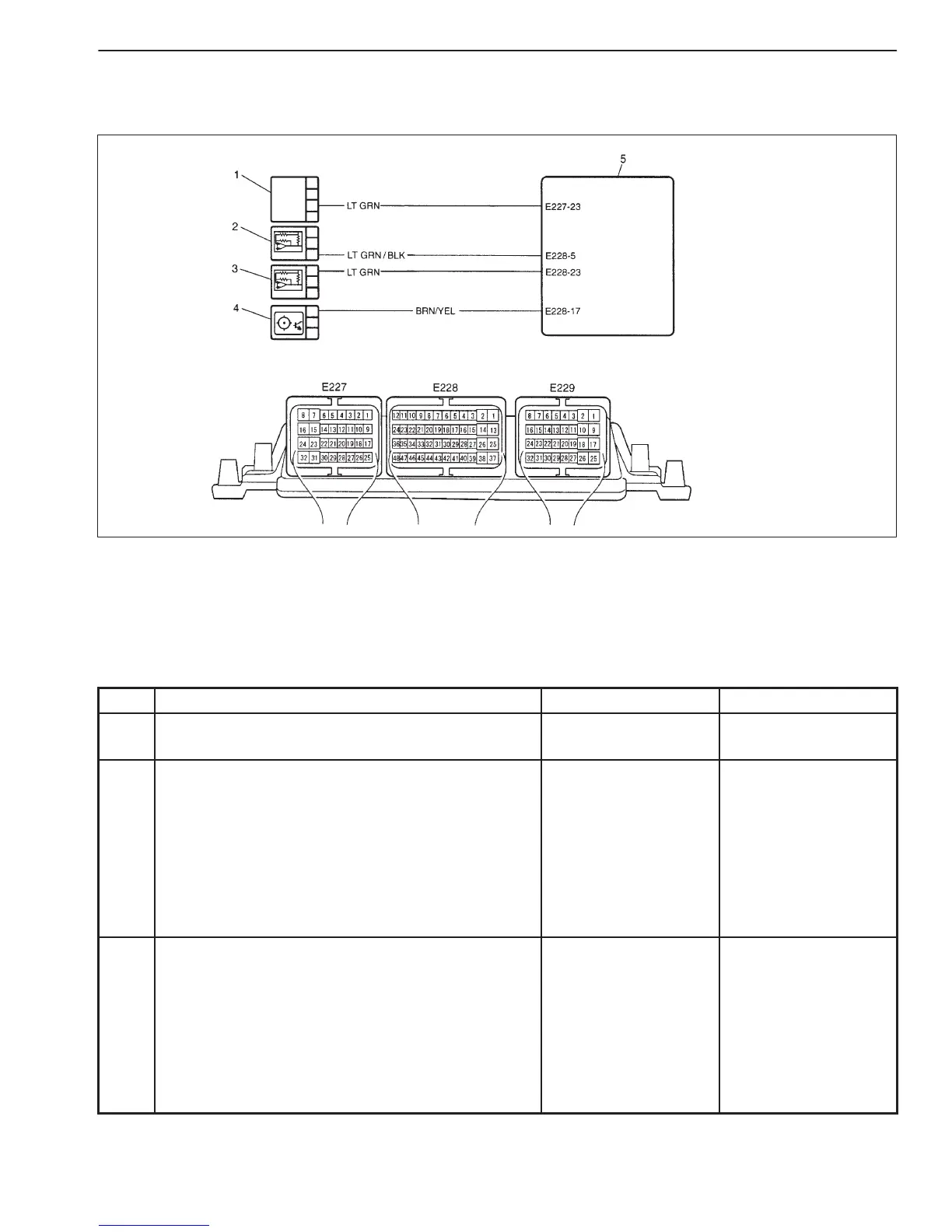
1. Throttle position sensor
2. Fuel pressure sensor
3. Intake air pressure sensor
4. Camshaft position sensor
5. ECM
ENGINE DIAGNOSIS (RHZ ENGINE WITH TRIPLE-CONNECTOR ECM) 6-1-45
DTC P1614 (P0560) SENSOR SUPPLY FUNCTION
WIRING DIAGRAM
DTC CONFIRMATION PROCEDURE
1) Connect scan tool to DLC with ignition switch OFF.
2) Turn ON ignition switch and clear DTC, pending DTC and freeze frame data by using scan tool.
3) Check DTC and pending DTC by using scan tool.
TROUBLESHOOTING
STEP ACTION YES NO
1 Was “ENGINE DIAG. FLOW TABLE” performed? Go to Step 2. Go to “ENGINE DIAG.
FLOW TABLE”.
2 Check TP Sensor Circuit
1) Disconnect connector from TP sensor with
ignition switch turned OFF.
2) Turn ON ignition switch.
3) Check voltage between “LT GRN” wire terminal in
TP sensor harness connector and vehicle body
ground.
Is voltage about 5.1 V to 4.88 V?
Go to Step 3. “LT GRN” wire shorted
to other circuits.
If wire are OK,
substitute a known-
good ECM and
recheck.
3 Check TP Sensor Circuit
1) Connect connector to TP sensor with ignition
switch turned OFF.
2) Turn ON ignition switch.
3) Check voltage between “E227-23” terminal wire
in ECM harness connector and vehicle body
ground.
Is voltage about 5.1 V to 4.88 V?
Go to Step 4. Faulty TP sensor.

 Loading...


